.jpg)
last update: 16/08/2010
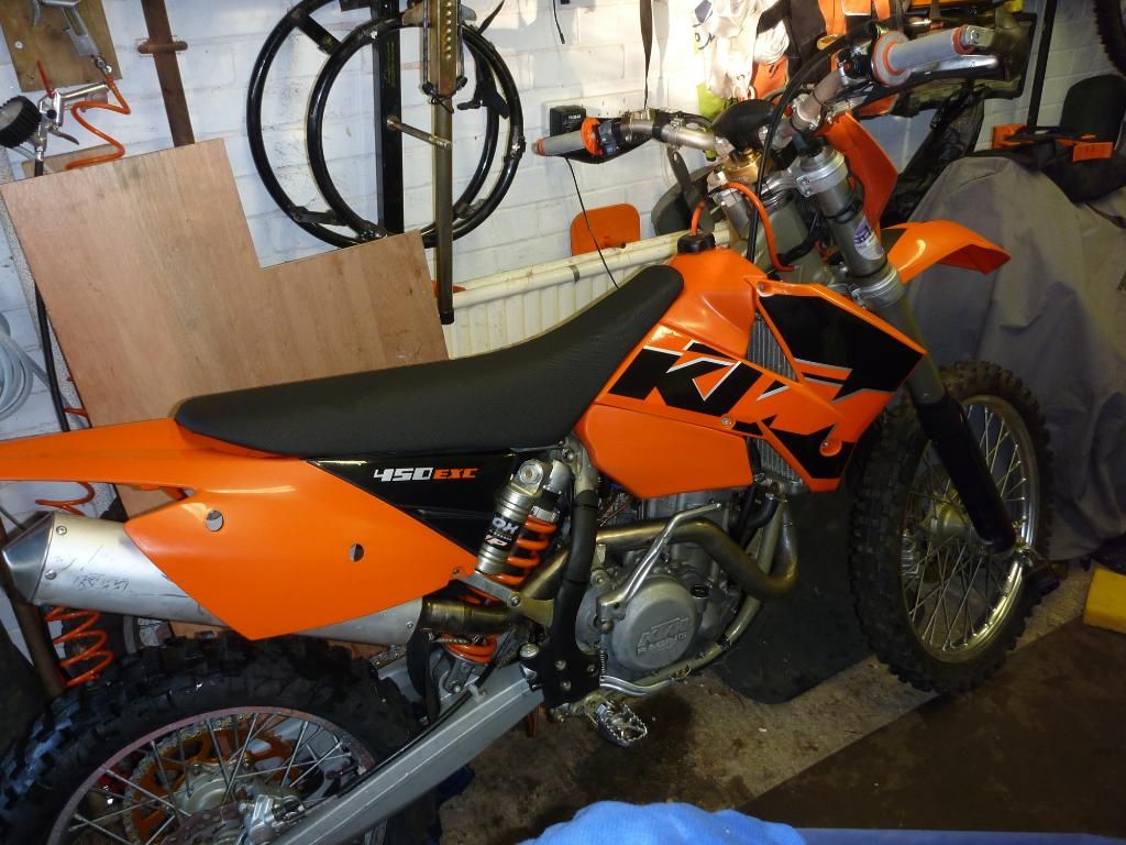
It's Finished!
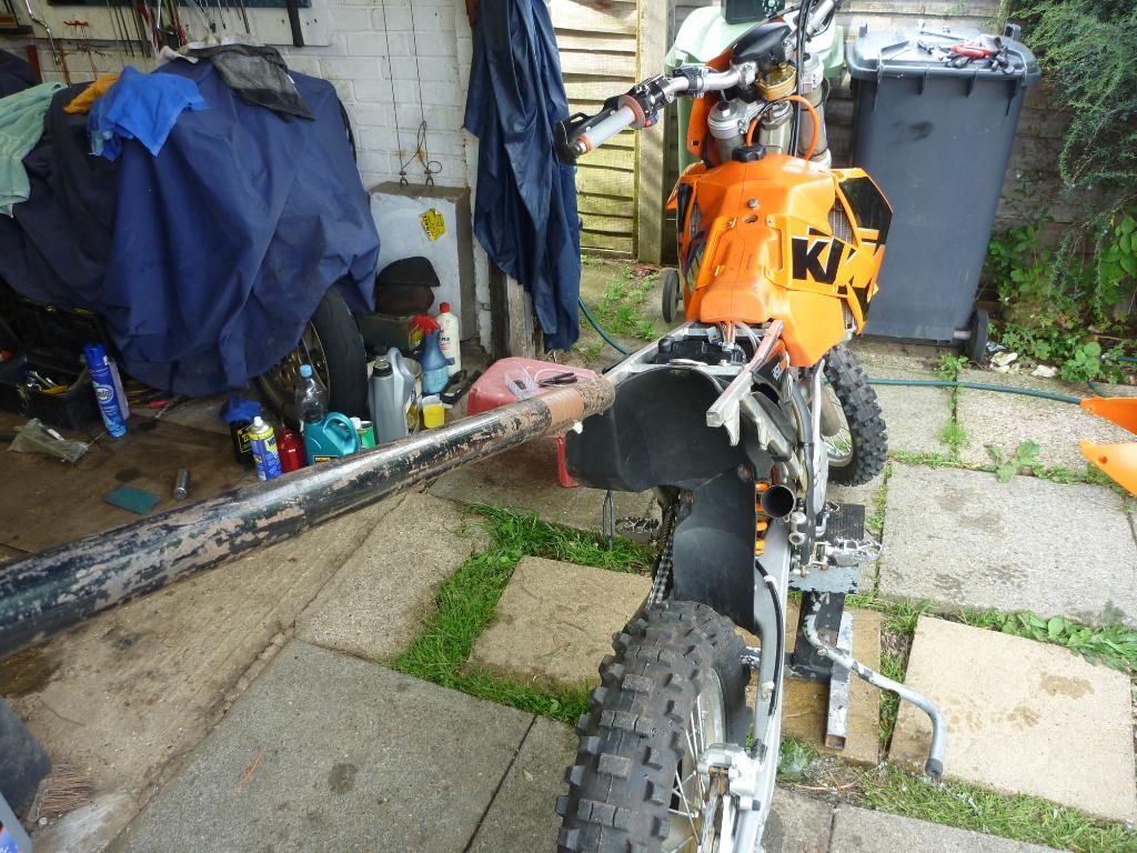
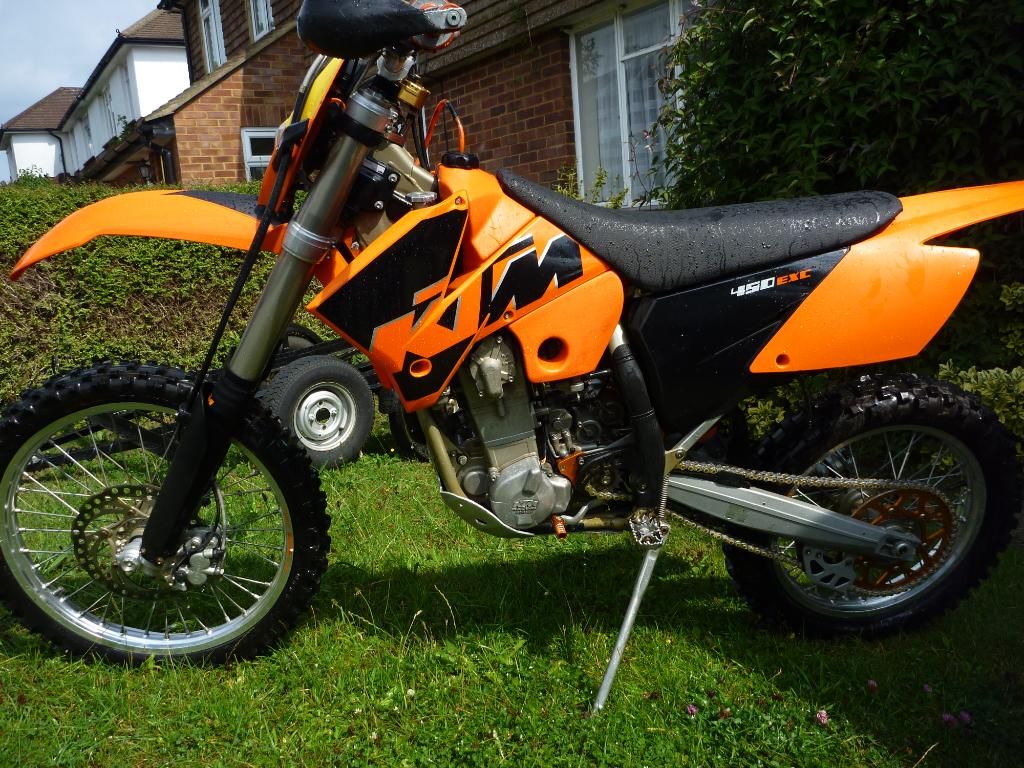
So I knew the day would come sooner rather than later. The KTM450 had near enough 500 hours on it and a lot of them were racing hours, so it was on borrowed time really. It was due for another valve check after the Ashby Enduroland event so I pulled it apart to give it a good clean before anything else. Spurred on by Steve’s new exc I decided to give my old 2005 battle wagon a spruce up. Next to Tony’s and Steve’s bike it was starting to look like a right pikey wagon! While stripping the bike down I made a list of all the small things that needed replacing.
-
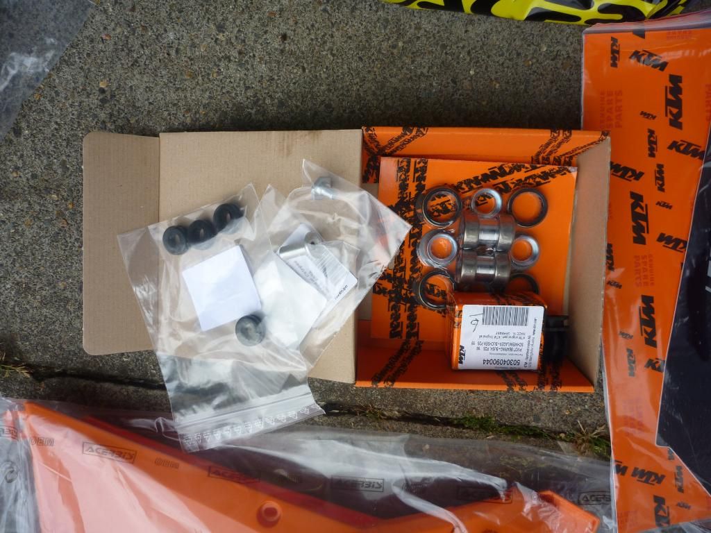
A new shock mount bearing set as this had become all gummed up again.
-
The exhaust can rubber mounting spacers. These were worn and old so the can wasn’t held very firmly.
-
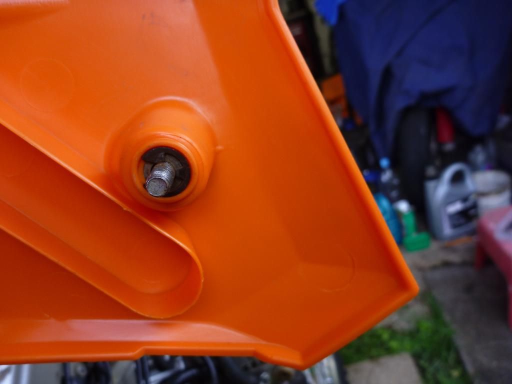
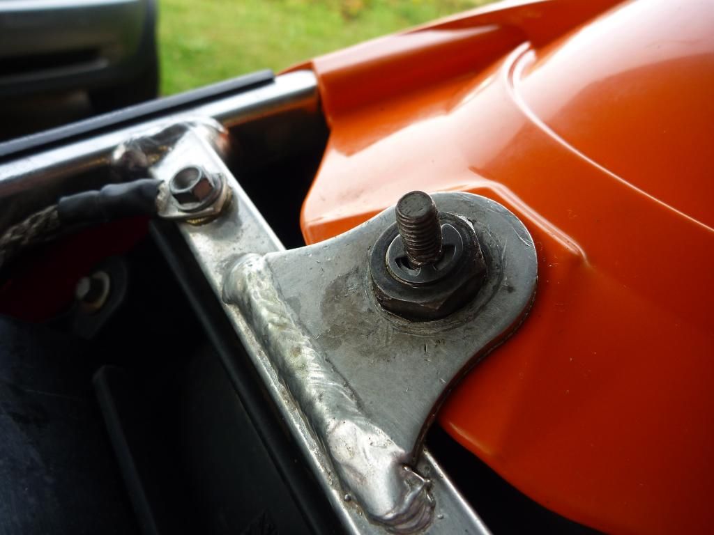
One of the aluminium spacers holding the petrol tank rubber mounting bungs was cracked as well so that was ordered too.
-
A new seat cover as mine had got torn at the last chec race.
-
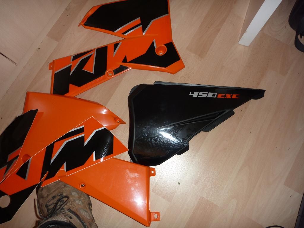
I ordered a set of new Acerbis plastics, woo hoo!
-
New air box cover.
-
New air box graphics.
-
Rad scoop graphics
-
Frame guards

ok i don't have a 'before' photo as i never intended to go this far!
.
These weren’t all ordered in one go but over several days. I’d decided to go a little bit further than just a quick clean up, and I was making a list as I striped down and ed. One thing that really needed doing was the chain and sprocket set, so I popped over to ‘Abingdon Off Road’ to pick up a new kit. While I was there I also bought a new set of grips and somehow a new bling gear lever found its way into my bag as well.
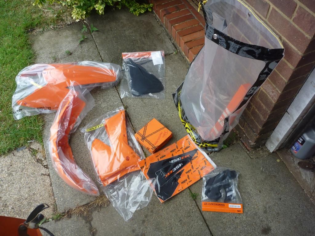
goodies!
.
more goodies and still plenty to come (unfortunately)
.
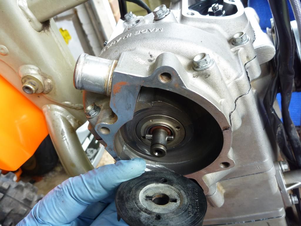
While doing some more work on the bike I tried to trace the source of the knocking sound at the back end. I’d fitted a new set of swingarm bearings less than a year ago so I was sure it could not be them. Taking of the rear shock I bounced up and down on it for a while without effect. This had also had a service not too long ago but something was making the noise and I needed to get to the bottom of it. I put the shock in the vice and loosened off the spring preload to check the damping. All seemed fine so I turned my attention to the swingarm once again. I pulled out the rear wheel and now that all the weight was off I could wiggle it around easier and I found the problem. Play in the bearings! Had I made a mess of replacing them before? Surely they could not have worn out so fast? Well no choice for it but to order up another set so I rang The KTM Centre in hemel and increased the order for the fourth or fifth time.
.
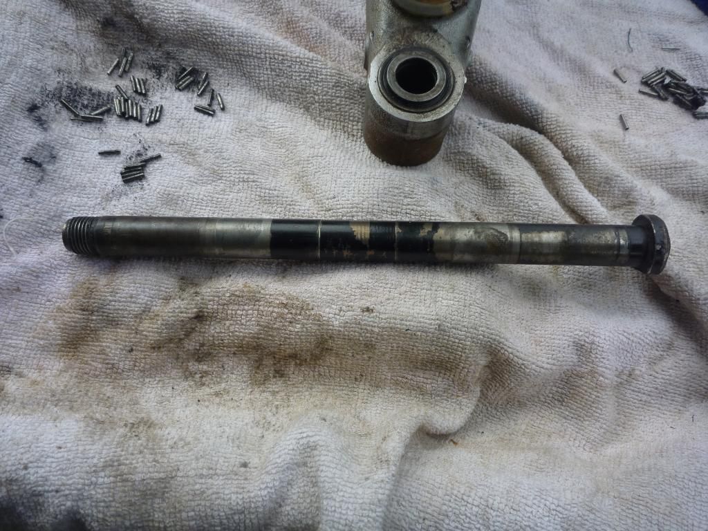
worn swingarm bolt - might not have been needed but no going back now i'm on a roll!
.
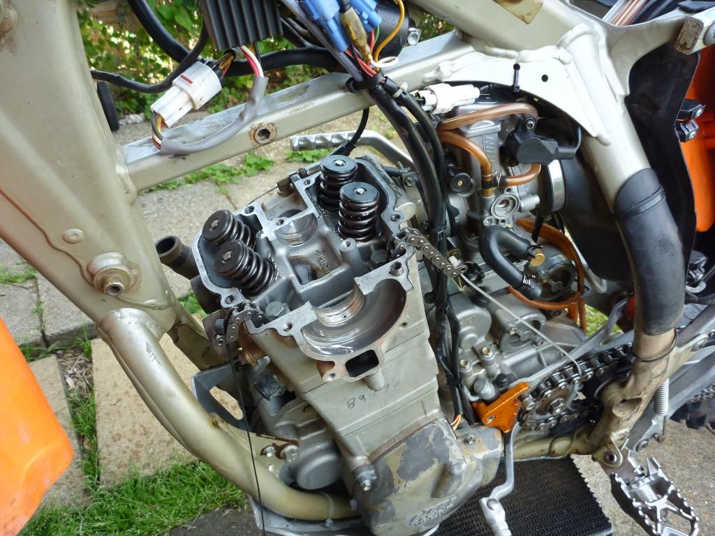
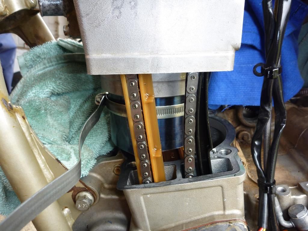
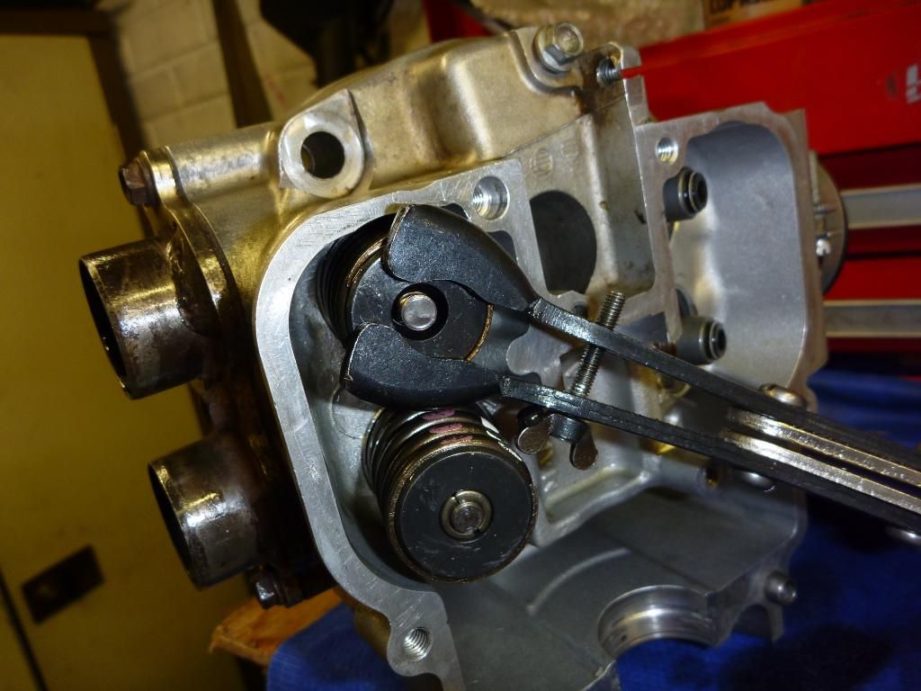
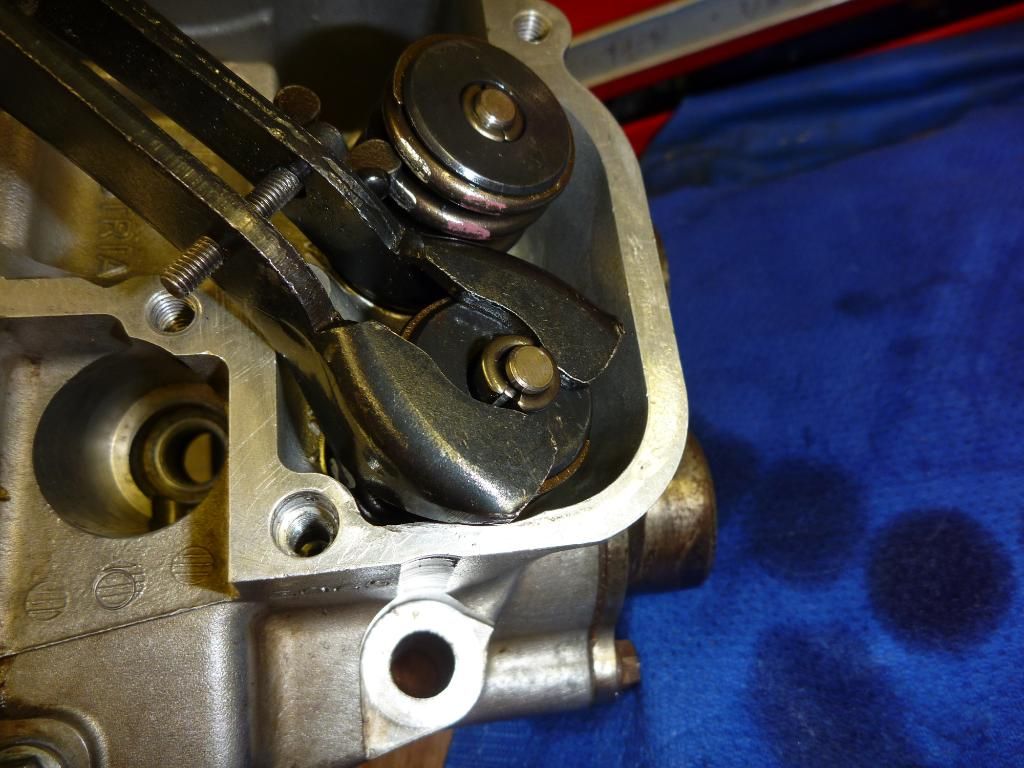
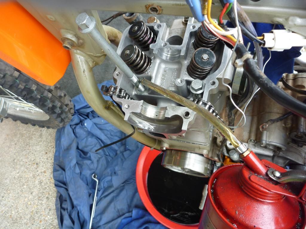
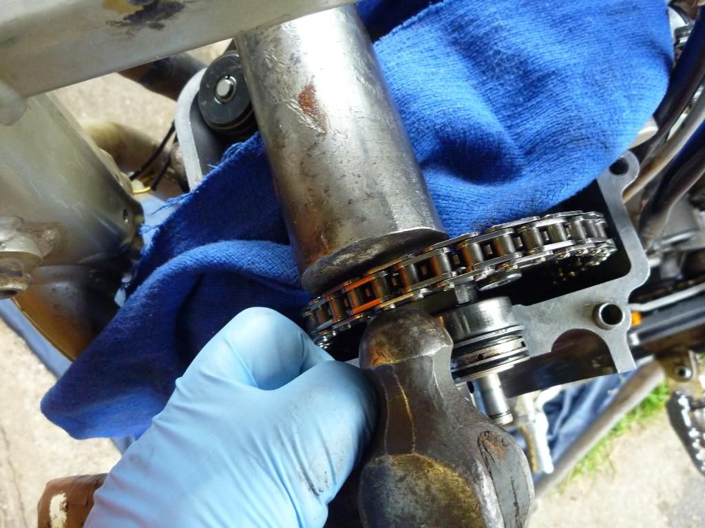
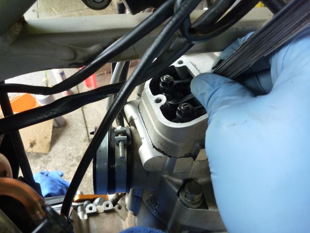
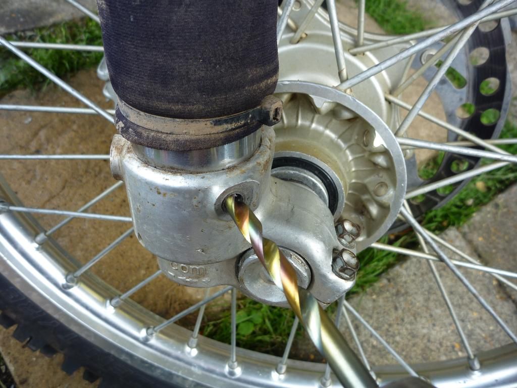
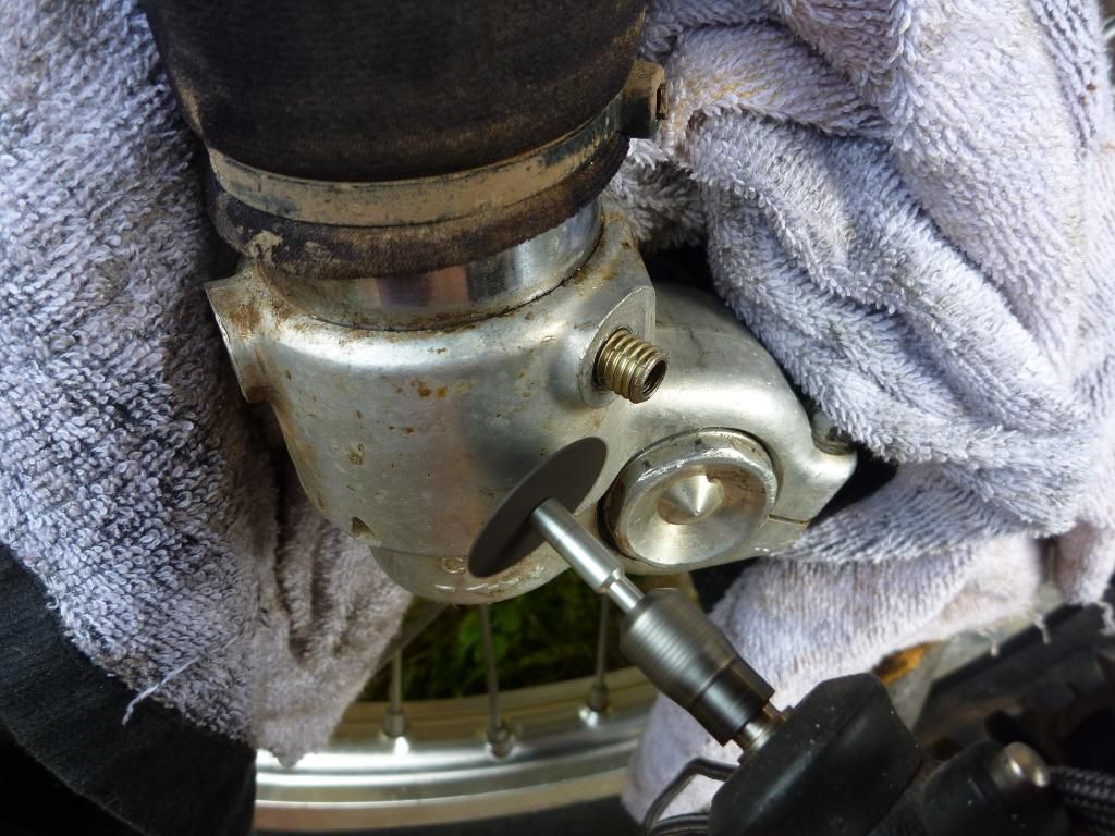
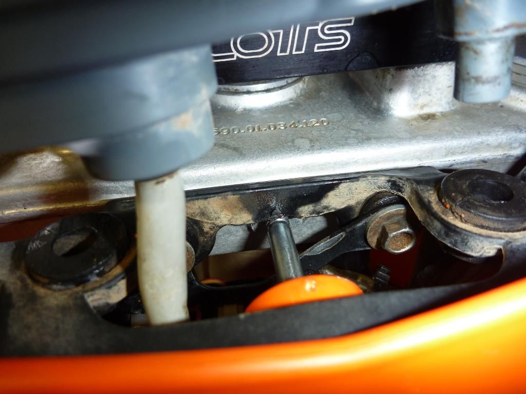
So while I was waiting for all of this stuff to come in I started on the engine ie adjusting the valves. Only one problem, I could not get enough adjustment on the off side inlet valve. I studied it for a while and was a little puzzled. Some closer inspection and a probe with the feeler gauge confirmed that the valve spring was touching the rocker arm. Something was awry mechanically, as clearly that should not be happening. Having only just replaced the one set of rocker arms I knew I could get the cover off easy enough so I pulled it apart and low and behold, there was I very small shinny spot on the arm where the valve spring had been touching. Mmmm the valves were plainly knackered so the quick tart up had turned into an engine re-build. Time to pack up and go get pissed :(
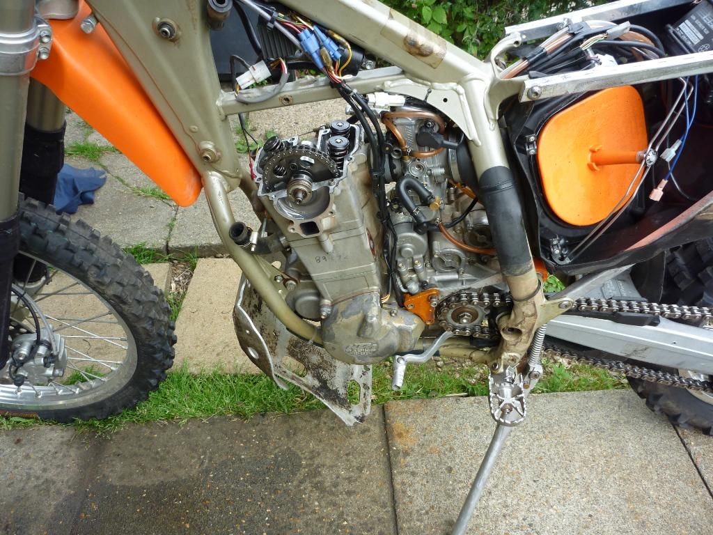
time to pull it apart! :(
.
also managed to break my new chain splitter the first time i used it. never used a proper one before. the instructions said to use the smallest one for timing chains. well the KTM one centre pin is too large for the bit that it gets push out into so that buggered that one up!
.
Airing the fact on the KTM forum that night one of the users (Kevin) offered me a high comp piston for almost half price so it would have been rude not to accept it. Not only that but he said he’d sort all the other parts as well, so the order was placed. Stripping the engine down revealed that the piston crown was in fairly good shape. Not too much carbon build up. But I’m skipping a bit here – why do some designers go out their way to make things hard to take apart? I think if you can’t get a ring spanner on it, then it needs re-designing. Why put a 8mm head bolt on the barrel so close that you can’t get a spanner on it? ok the starter motor needed to come off as well which I can live with, but come one, at least leave a few more mm to squeeze an 8mm spanner on!
.
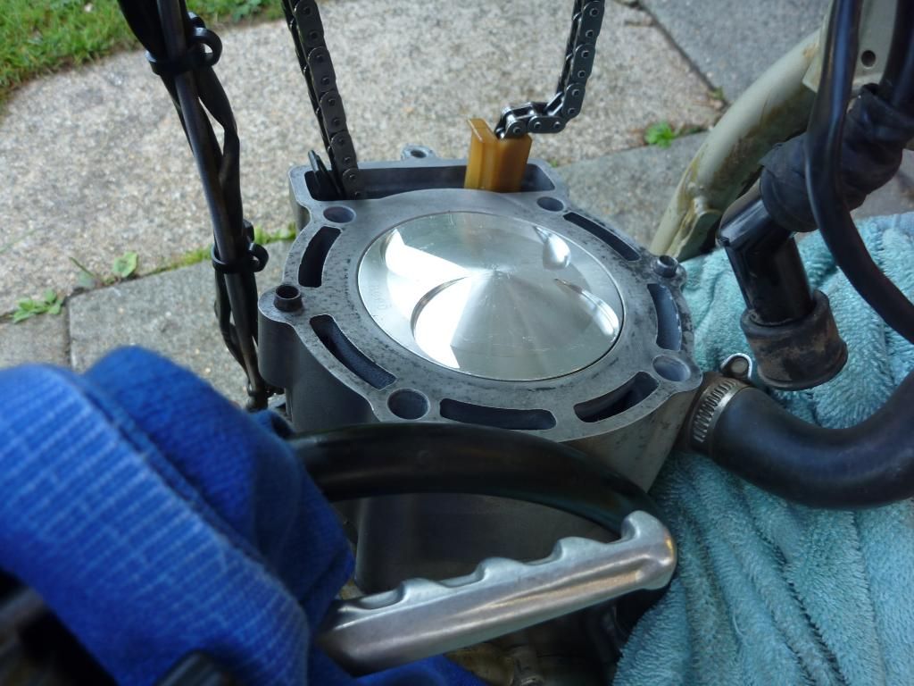
piston looks in good enough condition i suppose
.
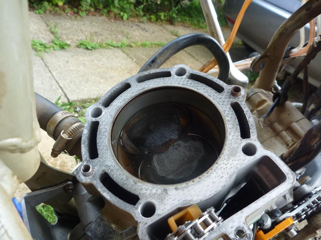
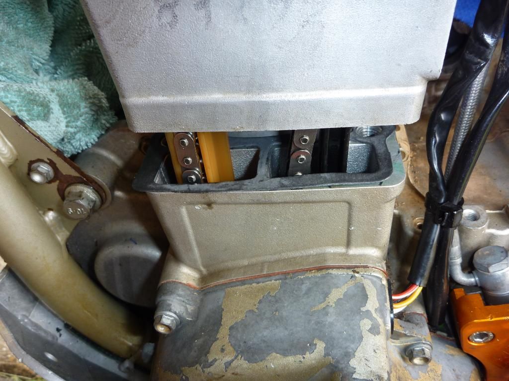
starter motor out and the 8mm bolt is removed using a mini socket and sliding t bar thingy, that was to get the head off, which in this photo is already off. pulling the barrel off now.
.
The piston crown may have been in good nick, but it was a different story once I’d pulled the piston out. The skirts on both side were badly scored and the barrel had some marks in it too. I light rubbing over with some wet and dry would sort the barrel.
.
small end. engine was running fine before this so i'm not going to take the bottom half apart.
.
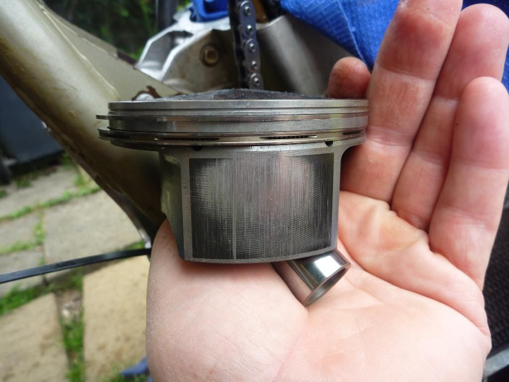
piston isn't too happy though
.
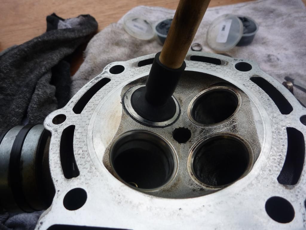
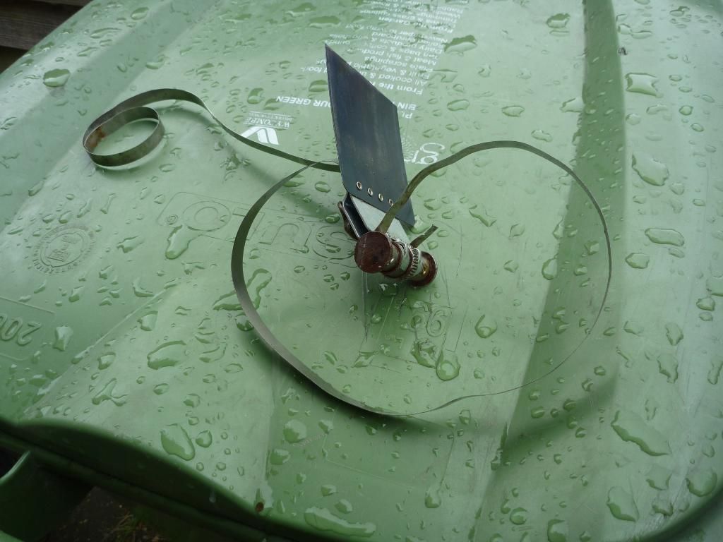
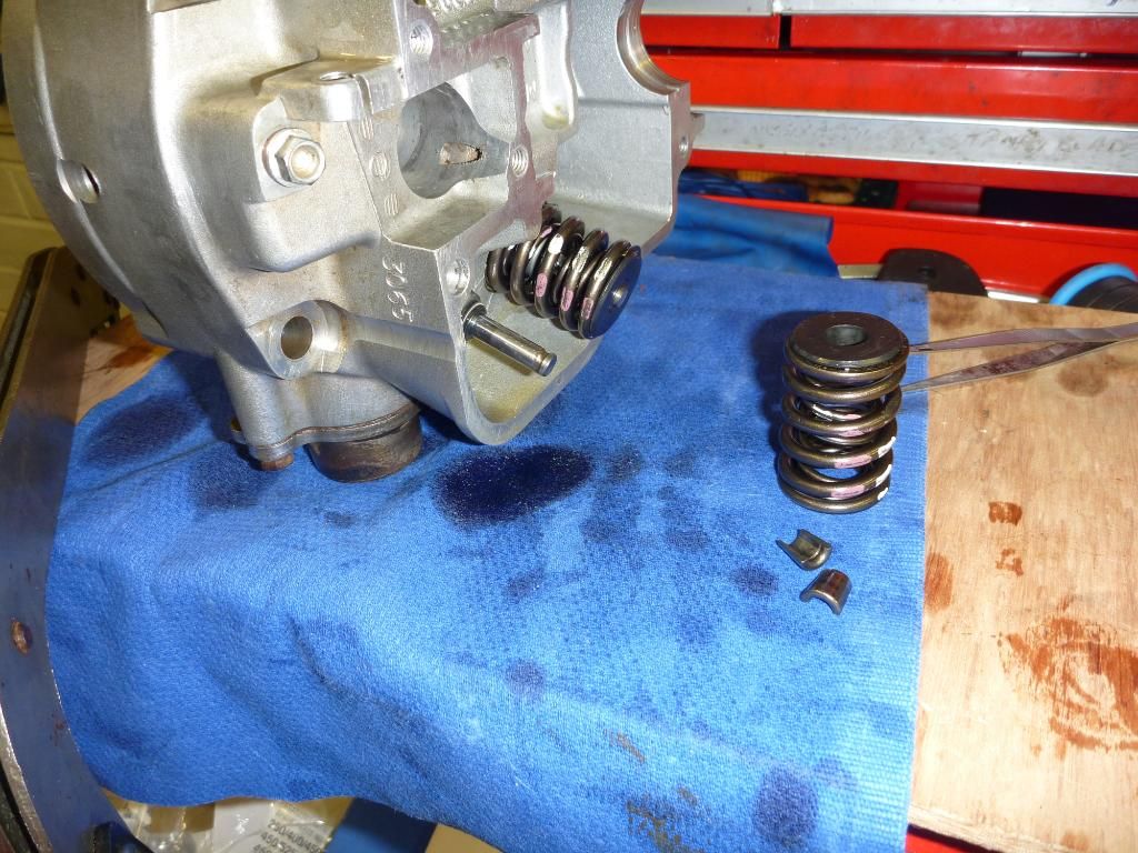
Next up was the valves – I had a valve lifter but no matter how hard I tried pushing on the handle the springs would not budge. In the end I decided I’d make up a ‘special tool’ using a large G-clamp. I tried it for size and tried to compress the springs. With a loud ‘crack’ the spring gave way and loosened off. For some reason the collets were jammed into the top retainers and once the seal had been broken with the g-clamp I was able to use the valve lifter to compress the spring enough to extract the retaining collets. This revealed the inlet valve to be as worn away as it could be, they were sharp enough to cut skin – no kidding!
.
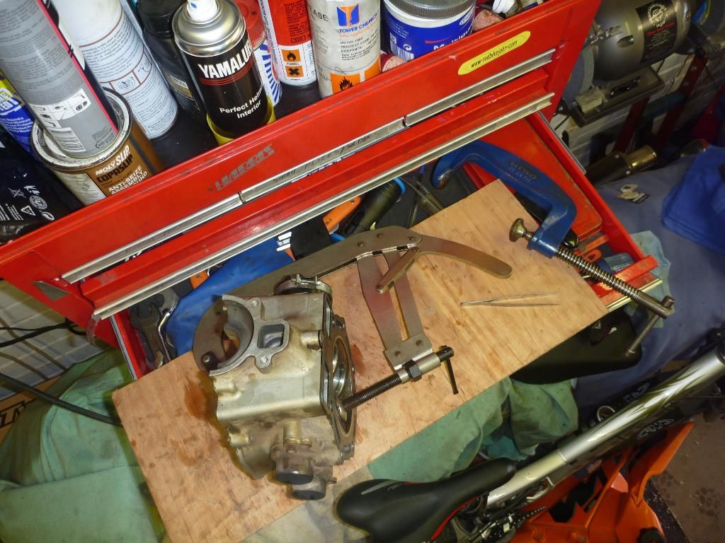
trying to get the valves out. G clamp is next!
.
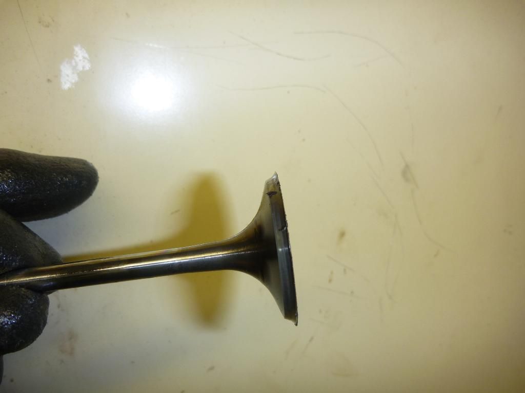
sharp as a knife!
.
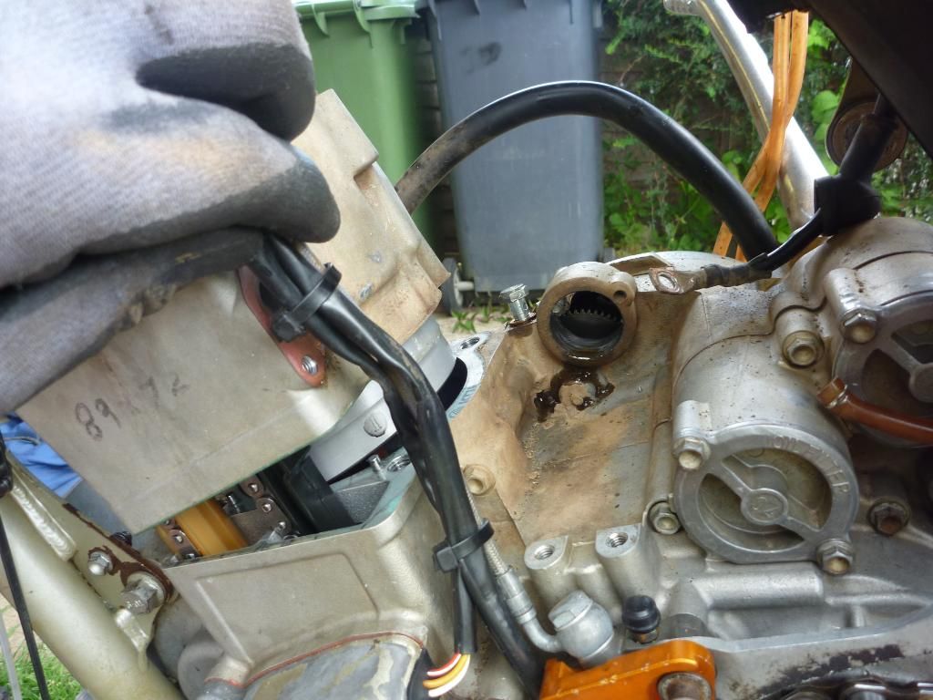
So the engine was in bits and I was waiting for the parts. In the meantime the body work and other parts had arrived (most of them) so I pulled the swingarm out to replace the shock mount bearings and to check on the other things like the swingarm bearings. I slid out the inner bearing race of the swingarm and could see no sign of wear n tear. So I was a bit puzzled why there should be play in the rear end. I fitted the swingarm bolt into the bearings and it wiggled around a lot......the shaft seemed to have worn. It has a black coating of something or other (Teflon?) so another one was ordered up. Boy this quick tart up was starting to make a big dent in my pocket!
So now I had the engine apart but no spares and the bike was up on a stand so I couldn’t do much else. I did fit the rear bodywork but I think that will have to come off again as the rear sub-frame is slightly bent. I think the tailpiece is sitting skew, mmmmm let me think, who crashed it last? STEVE!
new type doesn't quite fit 100% - yet
.
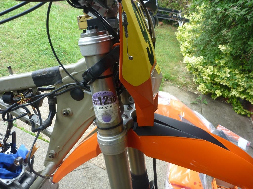
Next up I fitted the new front mud guard. The spares guy at The KTM Centre had swapped out the 05 model mudguard for the new 2010 style one. This looked great but the headlight doesn’t seem to sit quite far enough down so it looks slightly odd at the moment. To cure this I trimmed off some of the bottom of the headlight, but it didn’t help that much so I ordered a new MX board for the front. This has still to arrive and seeing as I almost never go trail riding any more it’s not a problem. I might even buy a 2010 headlight at some point to go with the mudguard anyway.
So now I was stuck. No swingarm bolt so I couldn’t more the bike around and no engine parts. At this point I seriously considered pulling the motor out and sending the frame off for coating. It really needs it but there are so many events coming up that I decided not to do it in the end. As it was I’d already missed the XC round at Canada Heights. I’d entered the event again as I really enjoyed it last year but had to pull out due to no bike (this hurt a lot).
Onwards with the re-build - I striped out the mini rollers from the swingarm bearing and meticulously cleaned them, then greased them up, ready for the new bolt. By now I was hoping to return the swingarm bearings as it didn’t look like I needed them anymore.
.
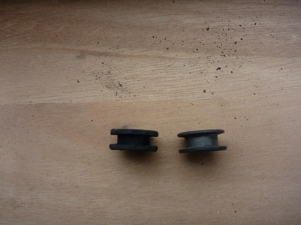
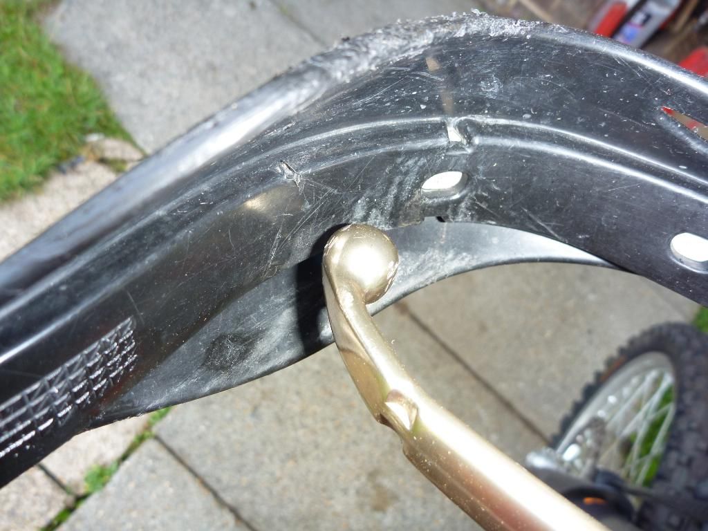
these little rubber grommets were replaced. new one on the left
.
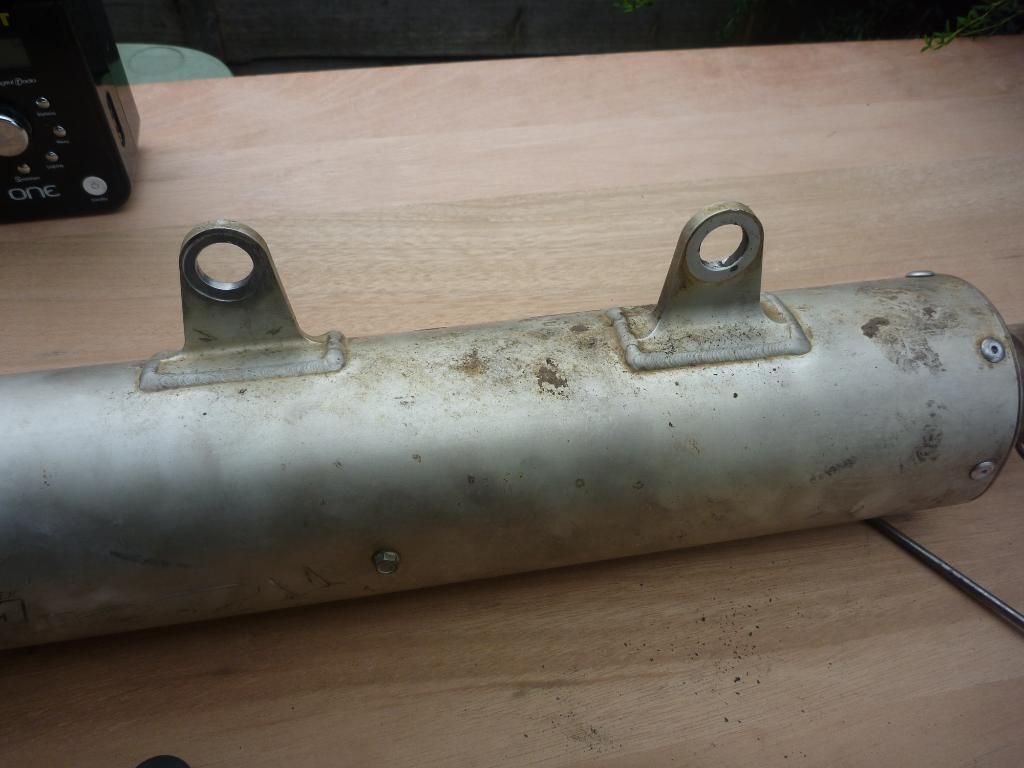
you can see where the worn one was rattling around and ended up cutting into the alum end can bracket
.
.
Still waiting for parts I turned my attention to the exhaust. This was looking pretty grim so I used a wire brush on the angle grinder to clean off all the baked on mudrust, that weird coating that is a mixture of iron like mud and rust. Note: always use goggles when doing this! Once the front pipe was cleaned up the end can was taken apart and the first set of packing replaced. I also fitted the new rubber mounting washers.
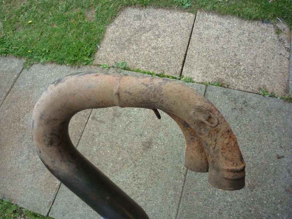
yuck - get the wire brush out
.
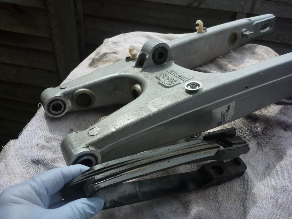
new chain guide needed.
.
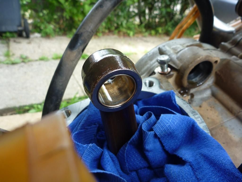
When the bolt arrived it didn’t have the black coating on it but had some sort of a bronze like colour to it, so I assume it was coated in something. Anyway the worst thing was that there was still movement on the shaft?! I can only assume that having a little bit of play in there before caused the inner bearing s to wear slightly. Whatever the cause, the new bearings were fitted.
For this job you need a bit of ingenuity to make up a press to ease them in carefully. I’d made one up last time so I dug it out again. I used a long M12 bolt (set screw is its proper name as it’s threaded all the way to the hex head). Then I used two nylock nuts turned around so that the round ends fitted into two washers. These washers would slowly press home the bearings and would bottom out on the shoulder once they were fully in place.
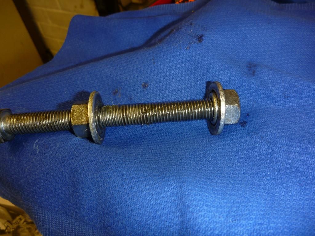
tool made to press home the swingarm bearing
.
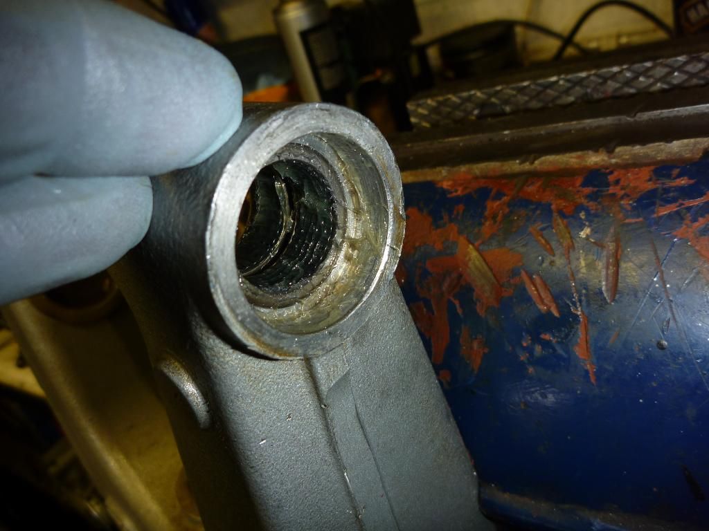
Both sets were installed but there must have been a small nick on the edge of one of the swingarm holes as when I slide in the inner race it tightened up way too much. There was nothing else to do but to try and press them back out again. This made me sweat a bit as it’s very easy to ruin bearings doing this sort of thing. Luckily I managed to not cock it up and once the swingarm was trimmed with the dremel they slide back in easily and the job was done.
.
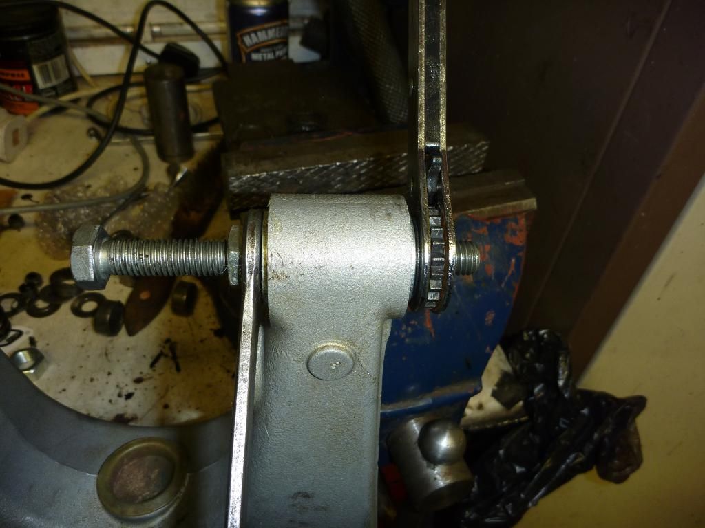
my tool in action! ;)
.
bearing pressed home. you can see the flat surface the washers press up against once they bearing are home
.
Swingarm back in, rear shock back in - this meant I could maneuver the bike around to enable me to fit the new chain and sprocket kit. The front one was fitted – then taken off again as I needed to fit the new swingarm chain wear guide, doh! This was another part that was bought once I noticed the one on the bike was pretty worn. I think that this is easily the fourth time this guide is being changed! Nice new shinny washers were used to fit it as well. Looking at the front wear guide it needs replacing too, as does the rear.....never ending stooooorrryyyyyyy!
.
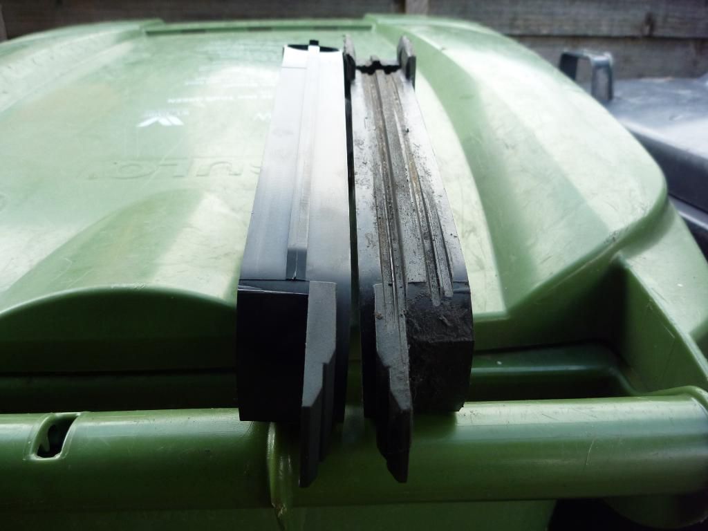
new and old
.

new front sprocket fitted - for the second time!
plus a new frame guard - don't want to damage the coating of rust!
.
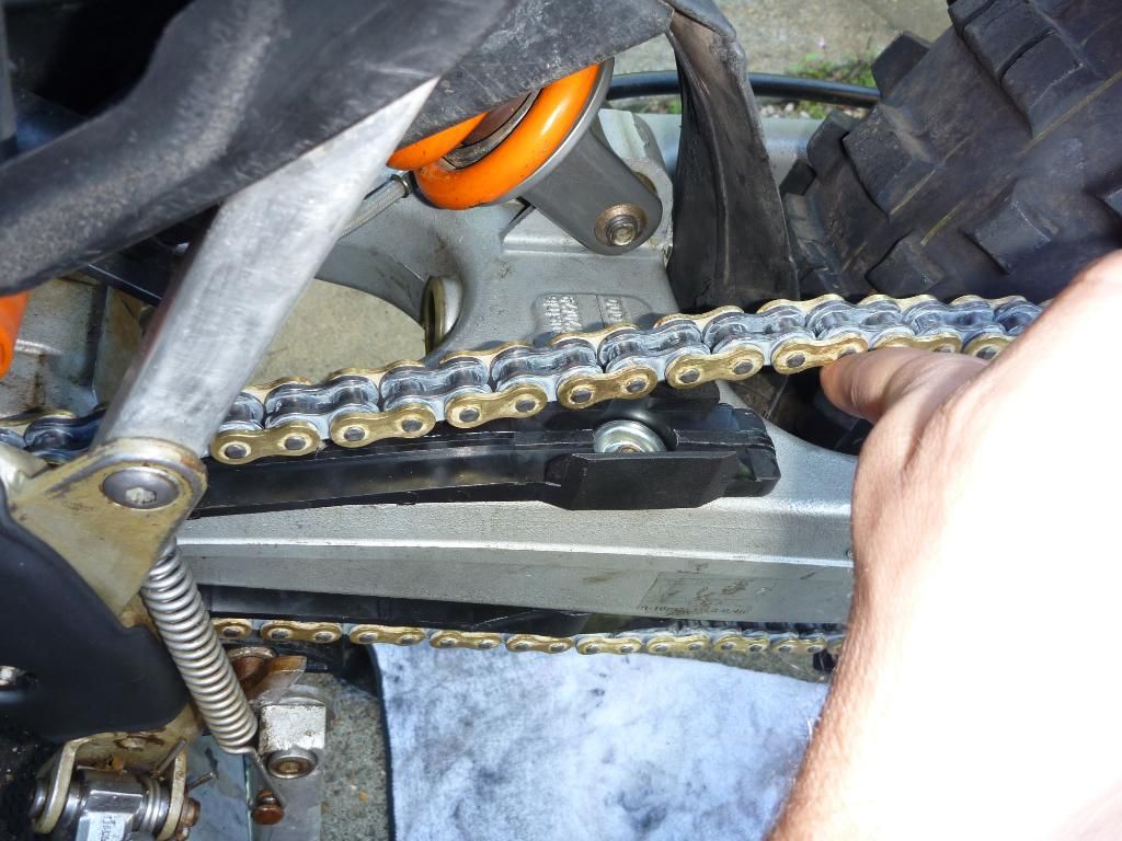
new chain and chain guide (with new washers)
.
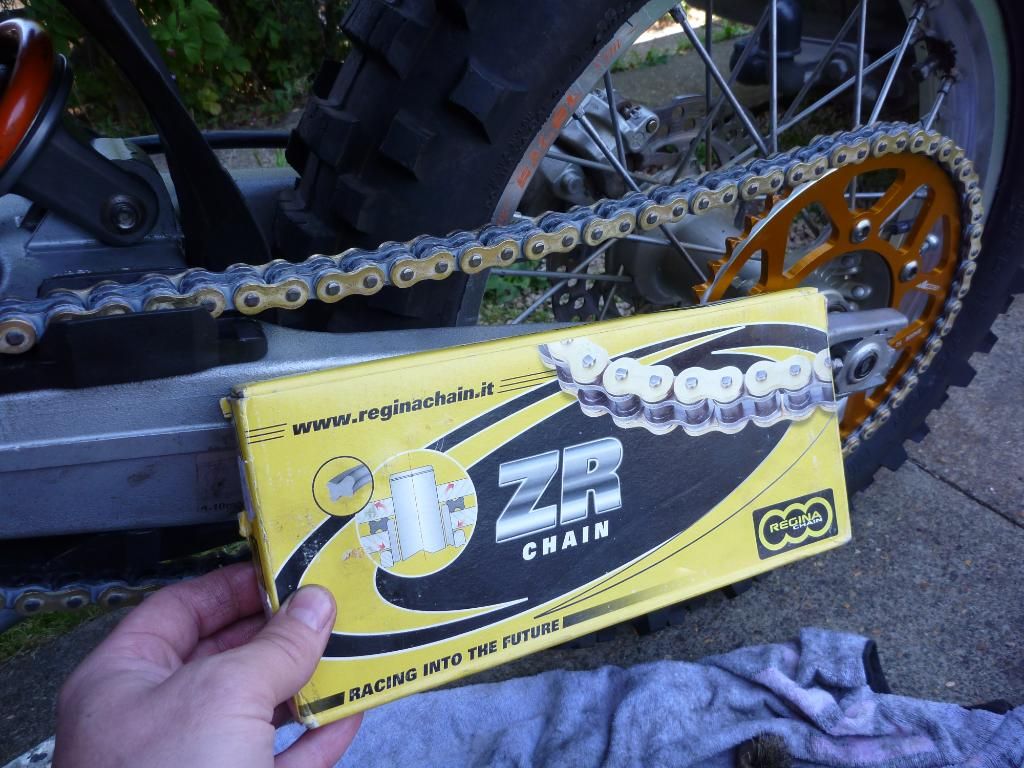
first time i'm using this chain. got it at a good price from Abingdon Off Road
.
The engine parts arrived so I got stuck in at the weekend by lapping the valves in. Boy what a laborious job that is. After a while a cheated a bit and used a battery drill. Yes I know you shouldn’t but my RSI in my right wrist was playing up so I didn’t have much hope of finishing it otherwise. I did cap off each one with a good dose of hand job just to make sure. In fact I might try and revisit it again this week. Once they were done I gave it a good clean off under the tap to clear of all the grinding paste.
.
rub a dub dub
.
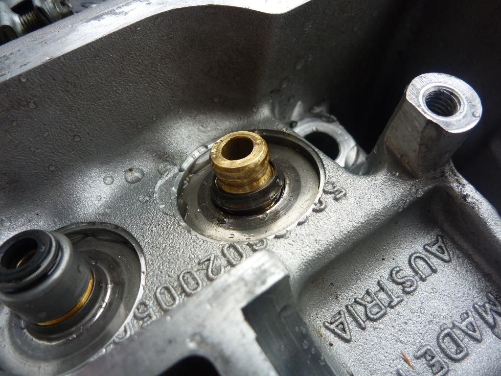
wear shim cracked in half
.
Removing the first valve stem seal revealed another problem. The wear shim under the off side exhaust valve had broken in half. A quick look in the spares book and a phone call to the dealer revealed that the part was only available as part of the valve spring kit! At the time of writing Kevin said he should have one and he’ll post it to me.
.
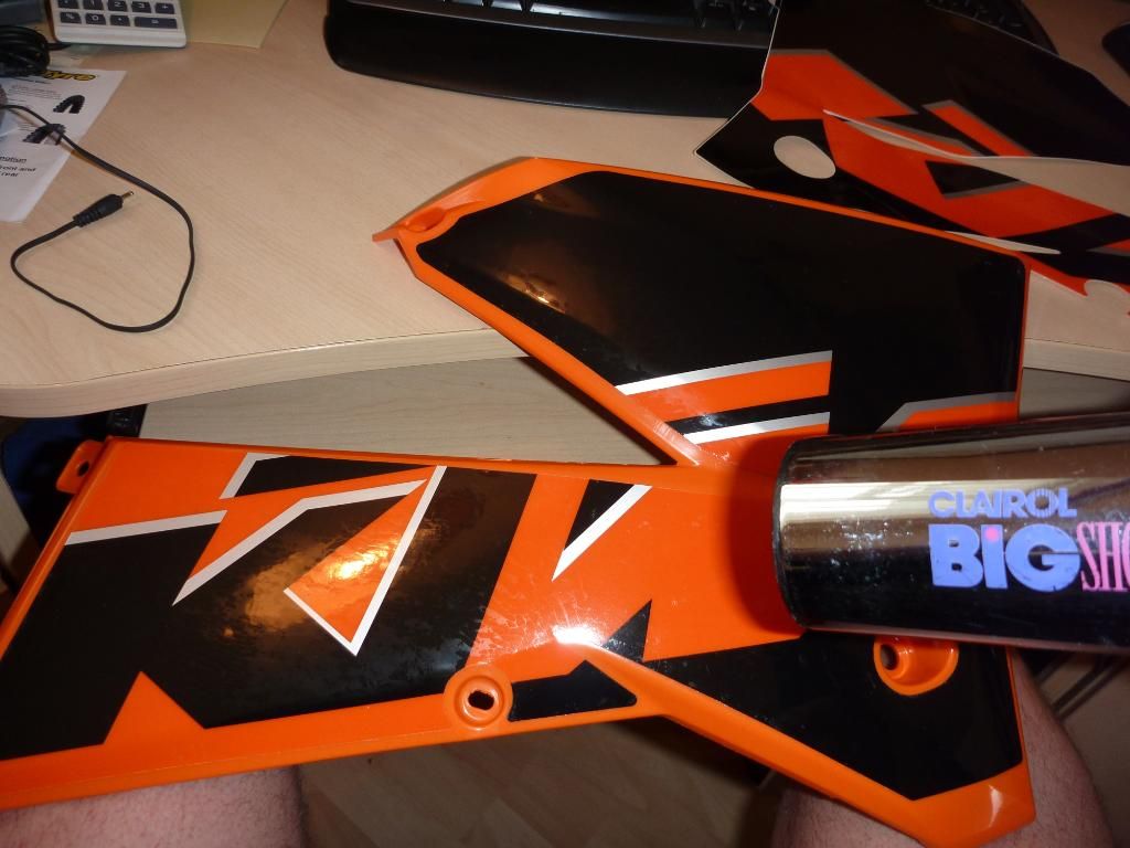
graphics sticky time
.
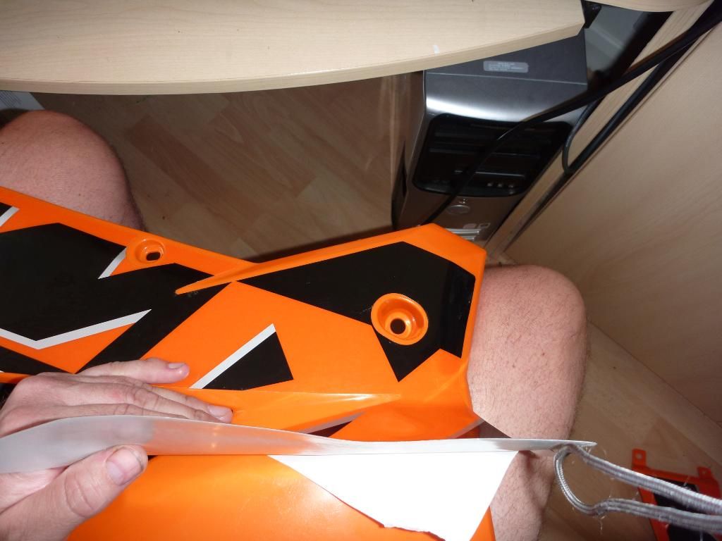
sticking the one half first. once i'm happy i'll peel off the other half and stick that.
yes i do have some shorts on!
.
So, pissed off again with the engine holdups I headed inside to fit the graphics to the new panels. The airbox cover graphic went on easy enough and once it was in situ I gave it good going over with a hairdryer. The rad scoop graphics are a lot more complex so I only removed the one half of the backing first. It took a few goes to properly line up the holes and edges. Once I was happy it was lined up I pulled the rest of the backing off and completed the sticking. Another dose of hairdryer on the edges to make sure it stuck and the job was done – only it wasn’t. The edges keep on coming up and I’ve been keeping an eye on them and re-doing the hairdryer bit over the last few days. I seem to be winning as nothing was stickup today. I’m beginning to think I should have cleaned them with a electrical cleaner first (I read that somewhere a long time ago) but seeing as they were brand new out the box I didn’t think they’d need it. Live and learn.
nearly done - one more to go
Next up was to fit the piston. I had a good look in the workshop manual and the Haynes one to make sure I didn’t get it wrong. It’s been a long time since I re-built an engine. The last engine I did any major work on was my katana 1168 back in South Africa in the 80’s. First of all I fitted the clip into one side of the piston. Like I said I’m out of practice and I struggled for ages trying to get that little bugger in! It didn’t bode well for the second one that would have to be fitted when the piston was in situ, not sitting on a workbench.
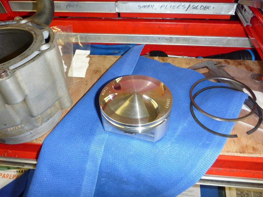
nice new shinny high comp piston!
Once the rings were installed I turned my attention to sorting out a piston ring compression tool. I had one of the standard sprung steel tools that you turn by hand, but that wouldn’t fit over the head again afterwards and it was too long (tall) anyway. The clearance between the rings and the gudgeon pin was so small I didn’t fancy trying to slide in the pin plus fit the circlip while all the time trying not to pull out the piston from the barrel. So no choice but to find another way of doing it.
.
home made piston ring compression tool
can anyone spot the mistake?
the discarded bit.
I did a search on the net and most were no good, so I chopped the old one up to make my own. First of all I cut off the ratchet mechanism, and then I trimmed the height of it so it would fit in the space beneath the barrel. Then I used a large jubilee type clip to compress it. Make no mistake it still wasn’t easy as the top ring is made out of superman like steel and takes a lot to compress. Two hours later and the barrel eventually slide down over the barrel. Then I spotted the bottom gasket – it was the wrong way round! How could I make such a mistake? Oh well I need the practice I suppose and indeed the second time it was much easier to get on.
aaaaggggg! the base gasket is round the wrong way!!!
.
Even though I got the piston/barrel fitted this morning I had a bit of a major mishap. The engine was locked in TDC with the hex head screw in the engine service hole in the crank. This meant that it would be a no brainer for putting it all together again. Only one problem – the crank moved as I was pressing down on the barrel to slide it over the piston! For some reason it could not have been in position properly. So now I have the job of ensuring it’s all in the correct position before turning it over the first time, something I could have done without.
.............................................
taken this morning. i forgot to show it before. nice new piston.
you can see the extra height in the crown for the high comp
.
So without the last necessary part for the head - today’s job was to replace the bar grips. Not only that but I needed to reposition and straighten the brush guards that had taken a few knocks recently (Steve!). There’s a few things that I like to do and would recommend to others reference bars grips and controls.
.
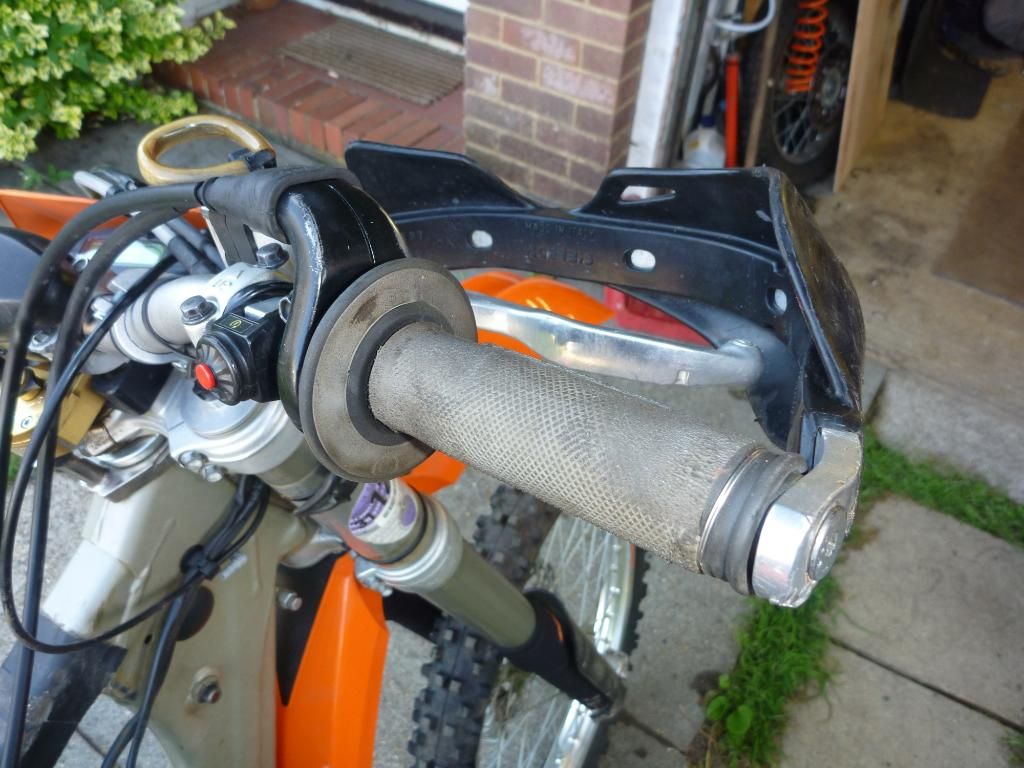
worn out grips and guards have taken a battering
First up is levers: now you probably all know this tip already but I like to keep the brake and clutch controls slightly lose. Not so much that they rattle around or constantly need pulling back into place, but lose enough that you can turn them around on the bars if you pull on them. This will ensure that when you have a spill they will tend to rotate on the bars instead of bending and breaking.
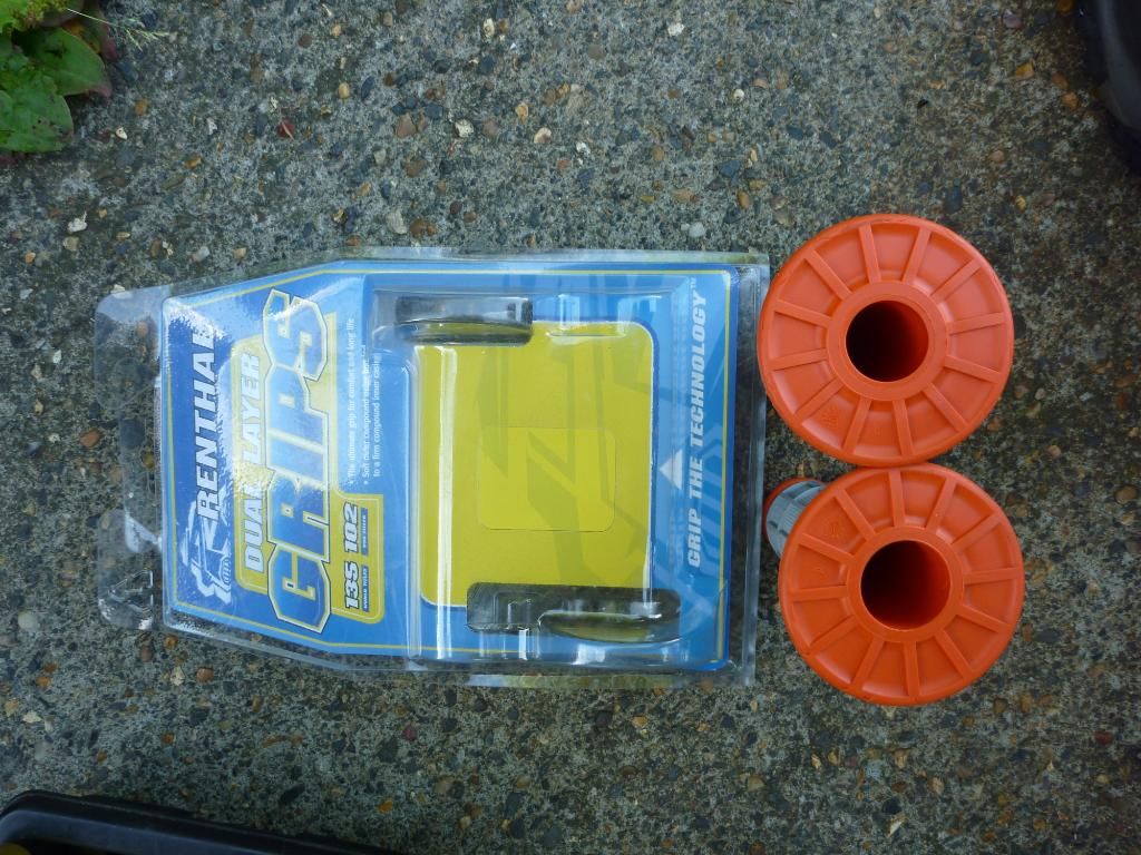
new grips. note that one has a slightly bigger inside diameter. that goes on the throttle side!
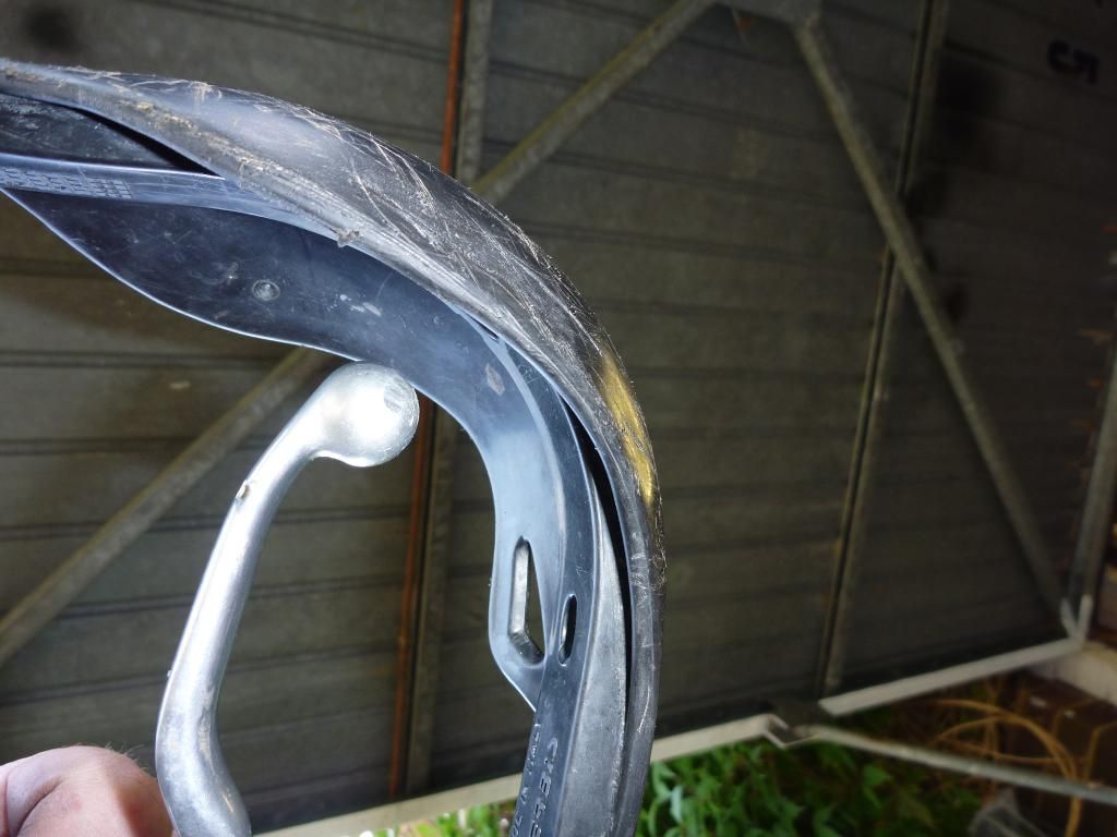
Grips I: use a knife to cut a small hole in the end first but after that I recommend you use a dremel to remove the last of the end cap without butchering the ends. I’ve seen so many grips that look like they’ve been chewed off by a rat – there’s no need for that!
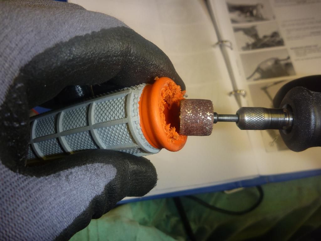
after the initial cut use a dremel. it does a real nice neat job without it looking like a rat chewed it off
Grips II: make sure there is enough room for the whole grip to slide on all the way. Not only that but make sure there is a decent gap between the throttle grip and the brush guard. If there isn’t then you might find that the brush guard will deform in a slight tumble and the plastic covering will interfere with the throttle movement, holding it open when you least expect it. A mate of mine used to have this problem all the time and wouldn’t have it when I tried to explain the problem.
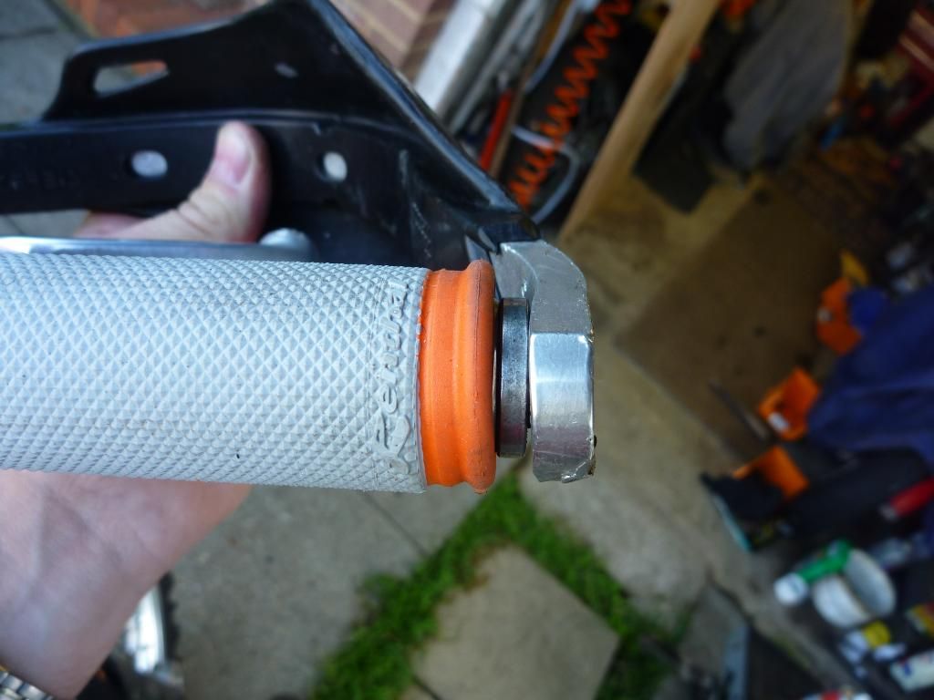
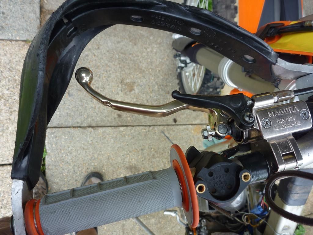
grip fitted with plenty of room at the end. see gap between the grip and the brush guard.
i've removed the plastic covering from the guard as it can interfere with the throttle if you have an off.
Grips III: make sure they can slide on for their full length. Don’t cut them down to fit the controls. Move the controls so that you can get the whole thing on. Why? Well I rode a mates bike once and he always used to get the skin rubbed off his thumbs. As soon as I got on it I noticed the grips were cut down and this didn’t give you enough room to move your hands around between the throttle housing and the brush guards – hence his thumb was constantly rubbing on the throttle housing and wearing the skin away!
enough clearance between the brake lever and the guard
.
.
So to start the job you just use a sharp knife to cut the old grips off (those of you not old enough to use a knife go and ask your mummy or daddy to cut it off for you). Then you need to clean up the bars/throttle with some emery cloth. This will get rid of any old glue and score the surface enough to enable the new glue to adhere. So the glue. You can use ‘grip glue’ but mine was finished (lost?) so I decided to use common old contact adhesive. I know some people like to use hairspray to fix the grips but I’m not too convinced. The old fashion kind that sets like glue once its dry is ok to use and it acts as a lubricant when sliding the grips on but I’m not too sure of its longevity. It has to be water soluble doesn’t it? Otherwise it’ll not come out your hair! So I recon water will creep in over time and erode it away. Anyway I stick to glue.

cleaning the muck and old glue off is a must. it also enables the new glue to adhere better.
.
Once the bar is clean spray or spread the contact glue over the part where the grip is going. Note – be careful not to get the overspray all over your new front mudguard! Make sure you have the correct grip for the side you are working on, as one of them has a slightly bigger hole for the throttle side. Now push the first part on as far as it will go. It’ll more than likely only go half way so I go to the other side of the bike and grip the front disc part of the grip and pull it over further which stretches the grip quite a bit. Now if you push it from the back and sort of push/squeeze it forward it’ll creep along the bars. Make sure it’s done fairly quickly as the glue will gip it tight in no time. Of course make sure the ridge side is not on the palm part of the bars!
.
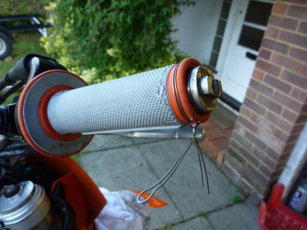
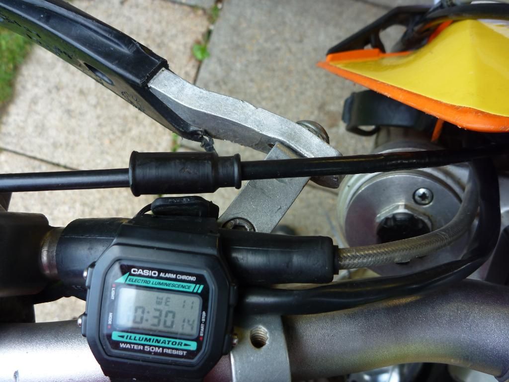
lockwire. tighten it up with a pair of pliers if you don't have a proper tool....
.... then take it off again as the wire is just on the bars and not the throttle tube. doh!
.
To act as a bit of extra security I use some lockwire on the bars too. A double strand of wire twisted with some pliers works fine. Make sure the ends are cut off and tucked away neatly. I tap them with a hammer to sink them into the material of the grips.
.
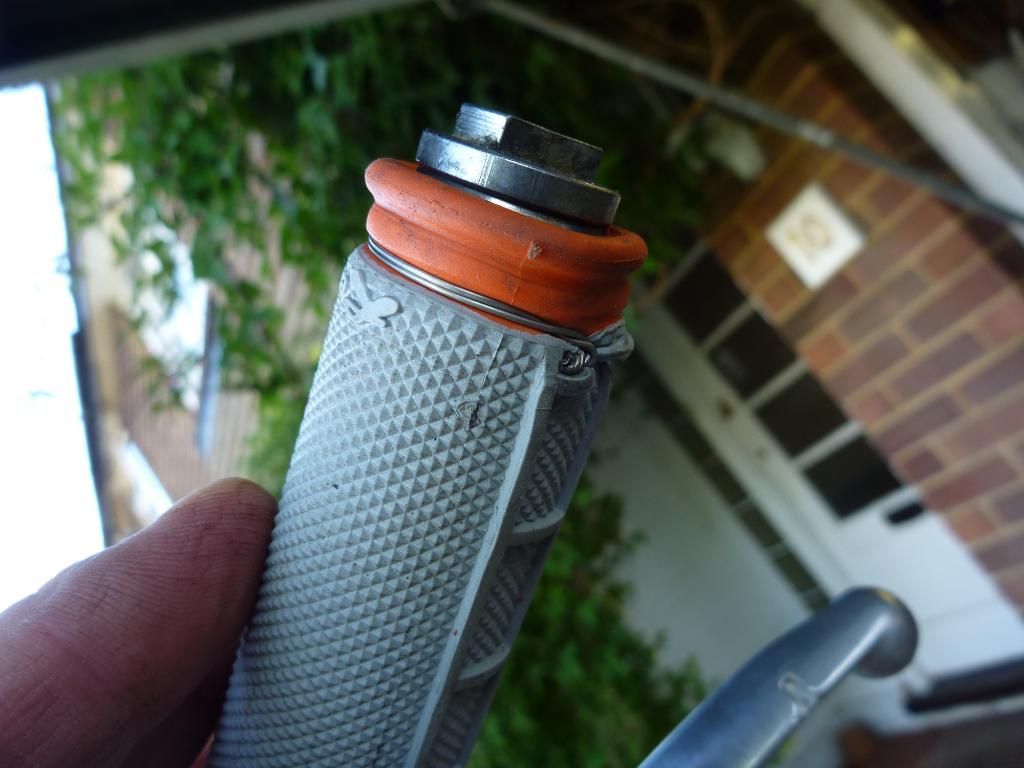
wire move slightly inwards and tightened up nicely. end bent over to protect your fingies
.
.
Ok the grips are done but the brush guards need a fair bit of straightening. If you look at the pictures you’ll see that they are a bit bent from some tumbles (Steve!) so a bit of straightening is in order. If you don’t keep on top of this they tend to bend in more and more and soon they’ll be catching on the clutch or brake lever. Also note that I’ve put a little bit of tape around the left bar so that the clutch master cylinder doesn’t migrate along the bars. I found this out one event. As previously mentioned I keep them (clutch & brake) with a bit of movement in them. The clutch master cylinder moved along the bars and started to catch on the guards which can cause clutch slip. Half a dozen wraps of electrical tape sorts this problem out.
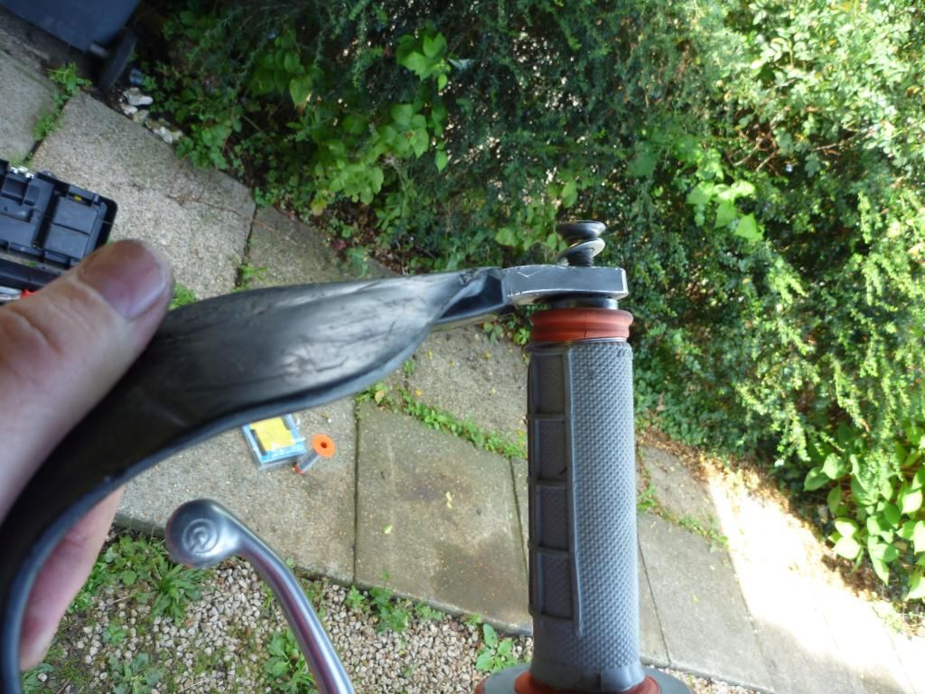
install a M8 washer under the main end bolt to help hold it (the guard) tight now that the countersunk cup has become worn.
on to the clutch side. here you can see the lever is nearly touching the guard as it bent/moved inwards
you can see the bracket has shifted over
A bit of backwards and forward to the vice soon had the guards sorted to a better fit and a couple blobs of nutlock will ensure the mounting bolts don’t come lose. Note in one of the drawings you see I fitted a washer to the bolt that goes into the end of the bar. That is because the softer aluminium of the guard has worn or deformed from use and the countersunk bolt doesn’t hold it tight. Pop a washer on and it moulds into the hole when you tighten it up, problem solved.
All striaghtened up in the vice but it took lots of backwards and forwards to get it right or acceptable.
Note I: the clearance of the lever to the guard is correct now. Note II: you can see the electircal tape that i've rolled onto the bars to stop the master cylinder moving toward the end too much.
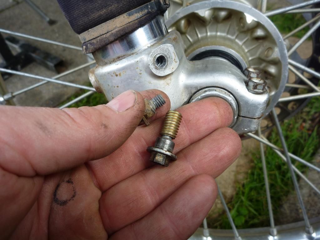
I did have one other problem and that is with the clamp mounting cap head bolts. They are underspeced at 5mm so are not really up for the job. The thread stripped in one but as they don’t go all the way through the bracket I just fitted a slightly longer one that used all the thread and another problem sorted. I was just cleaning up to go to work and I thought I’d put a bit of ‘back to black’ on the front forks guards and I noticed the middle bolt was lose. Yep the thread is gone. Luckily I have an insert that I’ll be able to use on that one and I’ll tackle that later. The wear shim arrived in the post just before I left for work so the head come with me for some extra TLC. Tomorrow the head goes back on hopefully.
..........................................
Finishing off the head
.
re-fitting the valves
.
As I said yesterday the head was first on the agenda this morning. I use the valve spring tool to compress the valve spring just enough to slip the retainers into place. It’s not too difficult to do but the first one was a little tricky, and then I got the hang of it again. The only thing you have to be very careful about is marking the matting surface of the head were the valve cover goes. This contact surface does not have a gasket and it relies on some sealing compound. That mean if you gouge the surface with the valve tool it’ll quite easily compromise the effectiveness of the seal.
.
Pic: as you can see here I made the mistake of doing the valve below the one that the tool is set up for now. The reason? Well now there isn’t a lot of room to manoeuvre the tool around and to keep it away from the head sealing surface. If I had done this one first I could have angled the tool above where the springs sit now. Then when it came time to do the other one there is room above the chain channel. Another lesson learnt.
.
Pic: once the spring is compressed pop in the collets and carefully release the tools handle. Job done.
It can get a bit tricky to get the collets in as the valve tool can move the whole lot around when compressed so the valve stem and top retainer are not central. You’ll have to put some pressure on the tool arm to make sure the retainer sits with the valve stem dead in the centre otherwise the collet will drop in too far and you not be able to get the other one in.
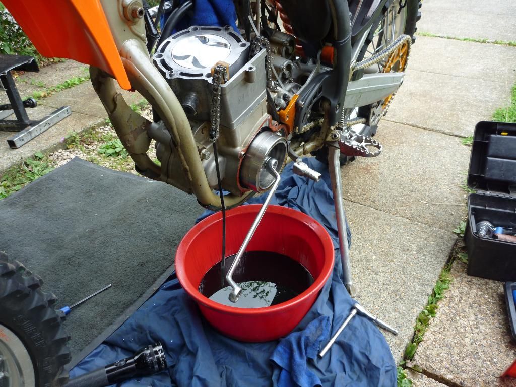
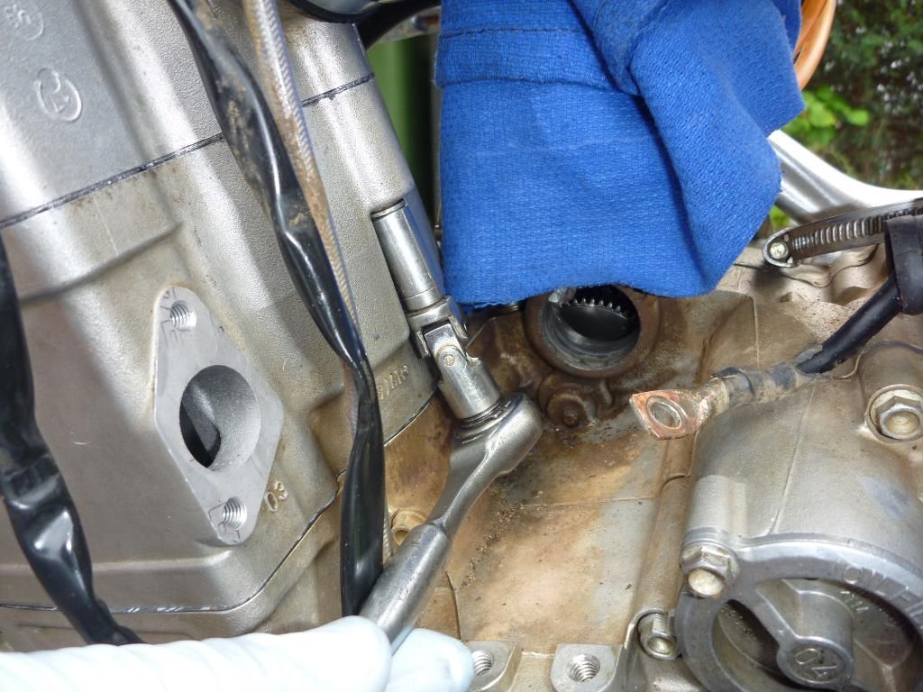
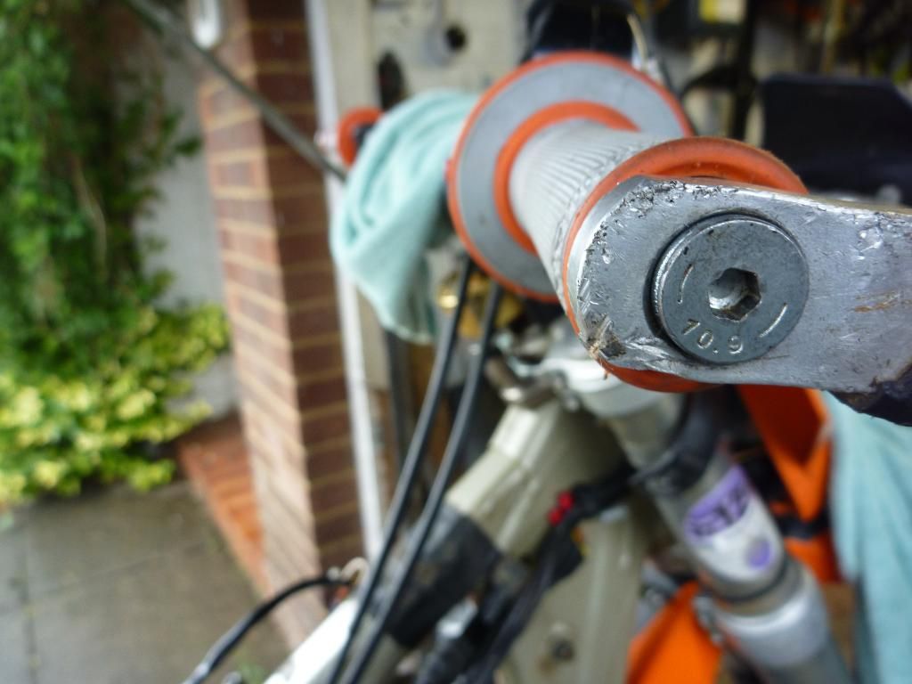
Once the head was all wrapped up it was time to get the crank locked back into position. For that I had to drain the old oil so I could get a spanner on the end of the crank. Once I could control the crank properly I removed the locking pin at the bottom of the engine and used a LED maglight to shine in and find the ‘hole’ that is used to lock the crank at TDC. The hole turned out to be a grove and was easily spotted as I already had it in the correct position.
.
spanner on the end of the crank so i can re-align the crank that moved
you can see by the oil the rings were well shot. black in only two events
.
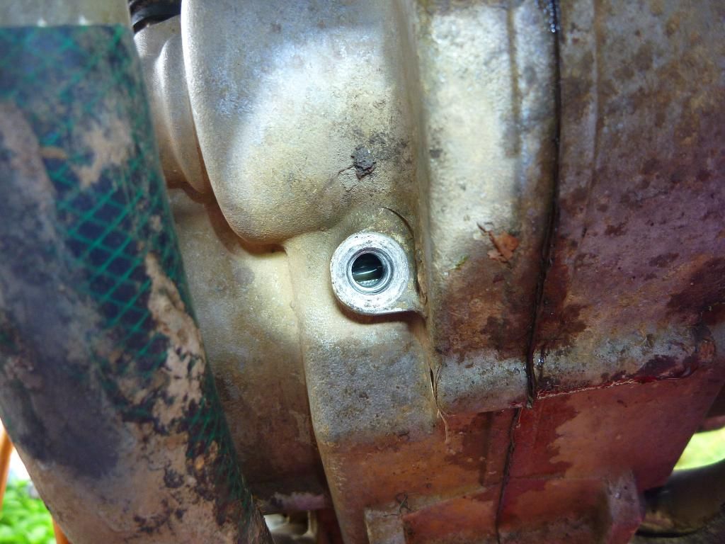
grove in the crank to lock off the engine
.
Next I gave the top part of the barrel a quick clean up with some wet and dry as I noticed it wasn’t 100% clean of old gasket. Making sure I had the new head gasket round the right way I fitted the head. The book recons to oil the main head retaining bolts so that is what I did and then tightened them to first resistance. Getting the torque drive out I nipped them up to 30NM by jumping across the opposites ie moving in a X pattern. I then upped the torque setting to first 40 and then 50NM as specified in the manual. Then checked them again just to be sure once they steeled down a bit.
oil the bolts before insertion
.
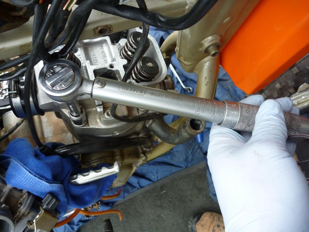
torque the bolts down in a X pattern
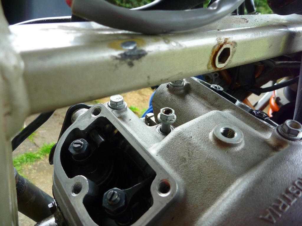
Next up was the pesky little M6 bolts. These need tightening with a 8mm mini ratchet and using a flexi head the one on the side and rear of the engine was no problem but the front one caused some problems as the driver was slipping. The shape of the engine cases meant I could not get the driver on 100% square. I then resorted to the sliding arm and trimmed one end down slightly (with the dremel) so that it would not catch on the cases.
the three m6 bolts can be a bit tricky to tighten
.
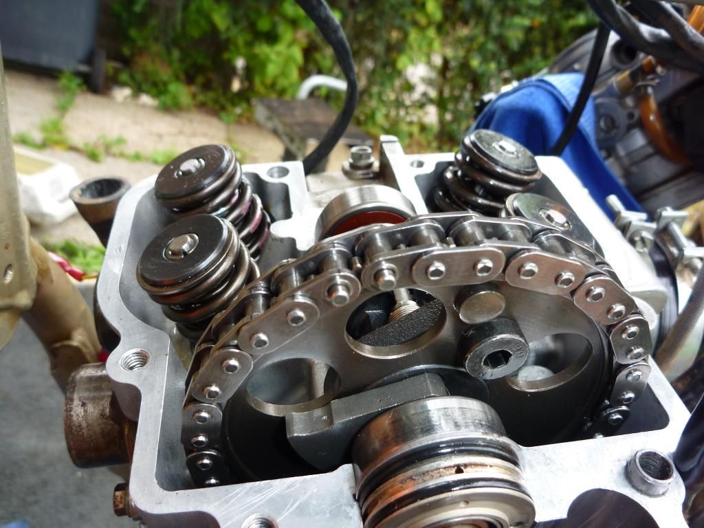
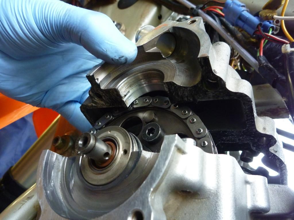
camchain in place. timing marks lined up with the engine case. drain hole in waterpump seals atthe top.
.
Fitting the cam back in place is easy as the two round marks need to be level with the engine cases when the engine is locked in TDC. Also note that the small hole in the water pump shaft bearings is placed at the top, as per the picture. Running short of time I just had a moment to slip in the rivet link of the cam chain before cleaning up once more.
............................................
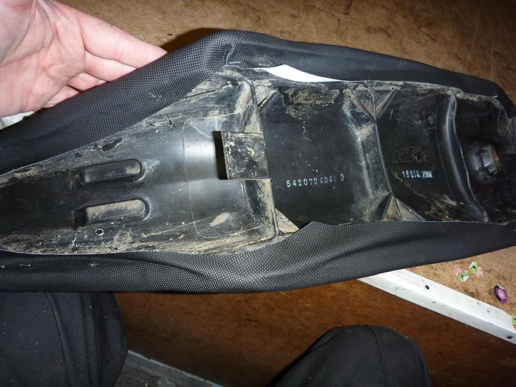
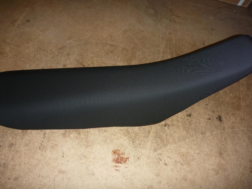
Seat Re-covering
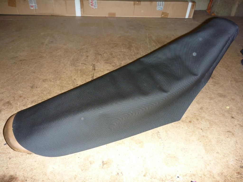
(no its not tired, it actually needs a new cover!)
.
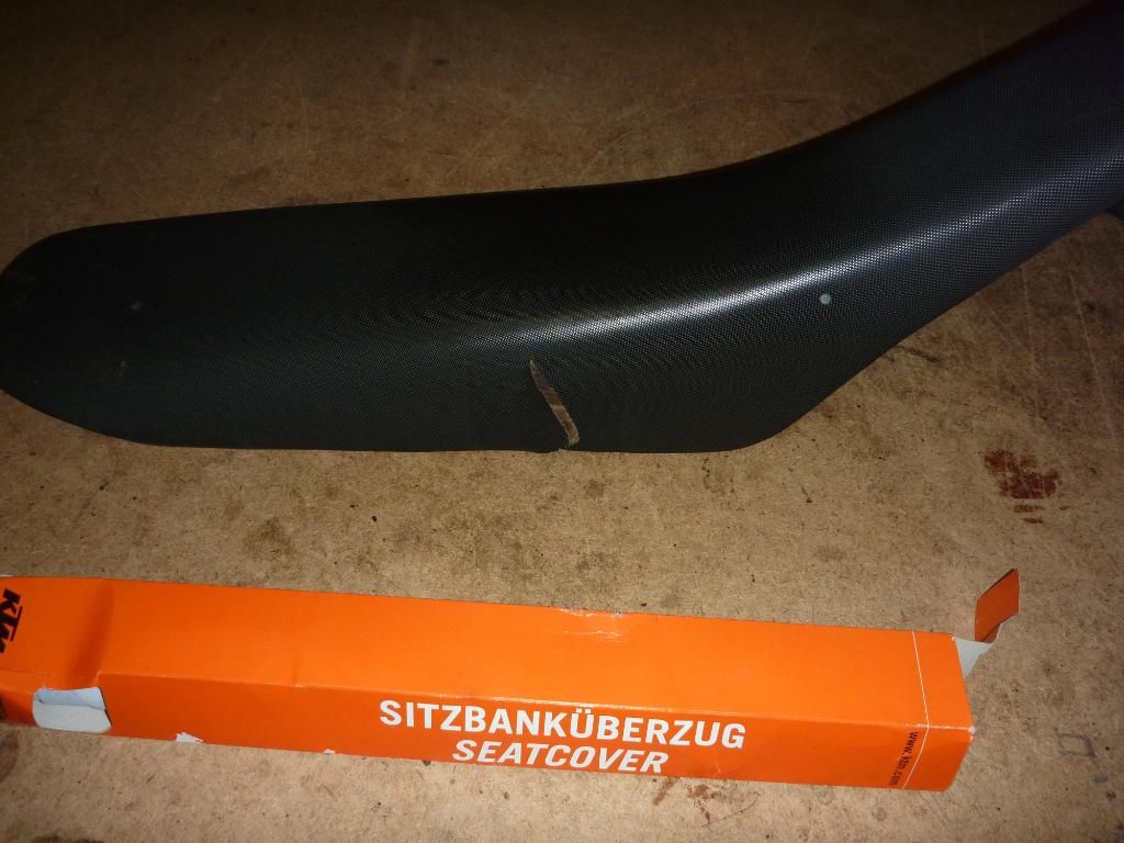
Here you can see the shinny surface of the seat in the flash. I intended to change it anyway as it was getting too smooth, the tear just sped up the timeline a little. Ok here it is in a set by step picture guide:
.
Right the first time I did this I was a bit concerned that I would not get it right. There is nothing worse than a seat that looks a saggy. It can totally spoil the look of the bike. However it’s always easier the second time round and this time KTM made it a bit less complicated by making the cover the exact size need (length wise). The first time I covered the seat the cover was too long so it was hard to judge exactly just how tight to pull it to get a good smooth fit. But now they cut it just the right size so you have to give it a good stretch to get it to fit, so it takes some of the guesswork out.
So why replace the cover? well it’s obvious in my case as the cover is torn. But if your bike has a few years under its belt or perhaps you use it a lot then by now the textured finish to it will have smoothed out. For normal riding this is fine but once you get into a wet n muddy enduro and start bouncing over some rough terrain you’ll appreciate the extra grip once the seat gets muddy. With a worn seat you’ll find you slide off the back of the bike and you’ll will be trying to control the bike with arms outstretched.
.
.
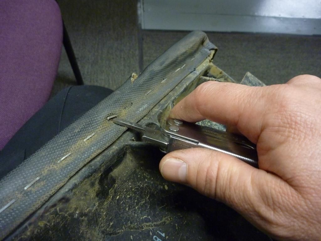
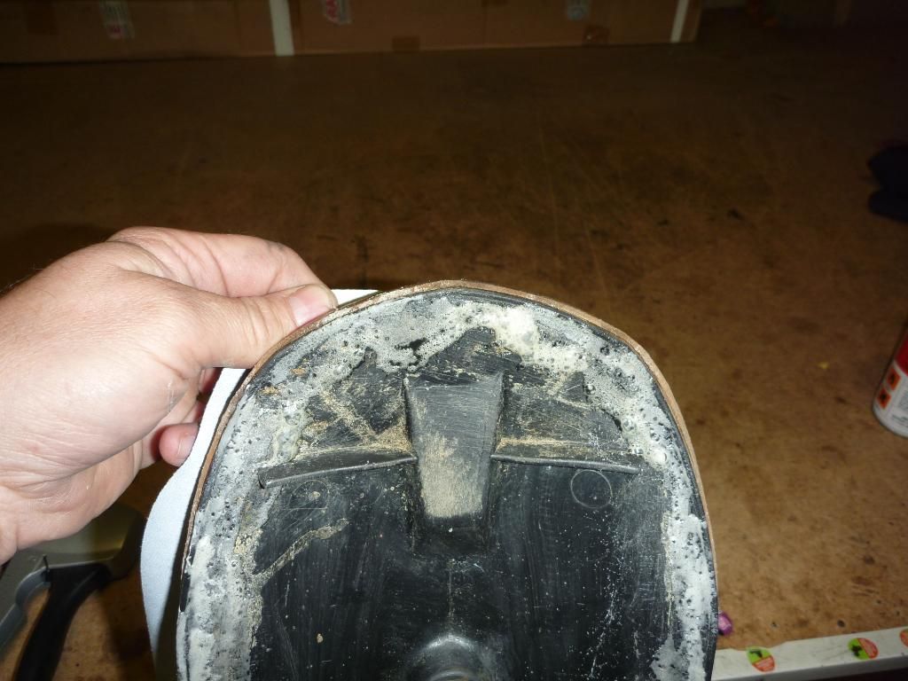
Step one: Easy, just remove the old staples with a screwdriver or tool of you choice. If you are working on your lap be careful you don’t slip and stab your leg!
.
.
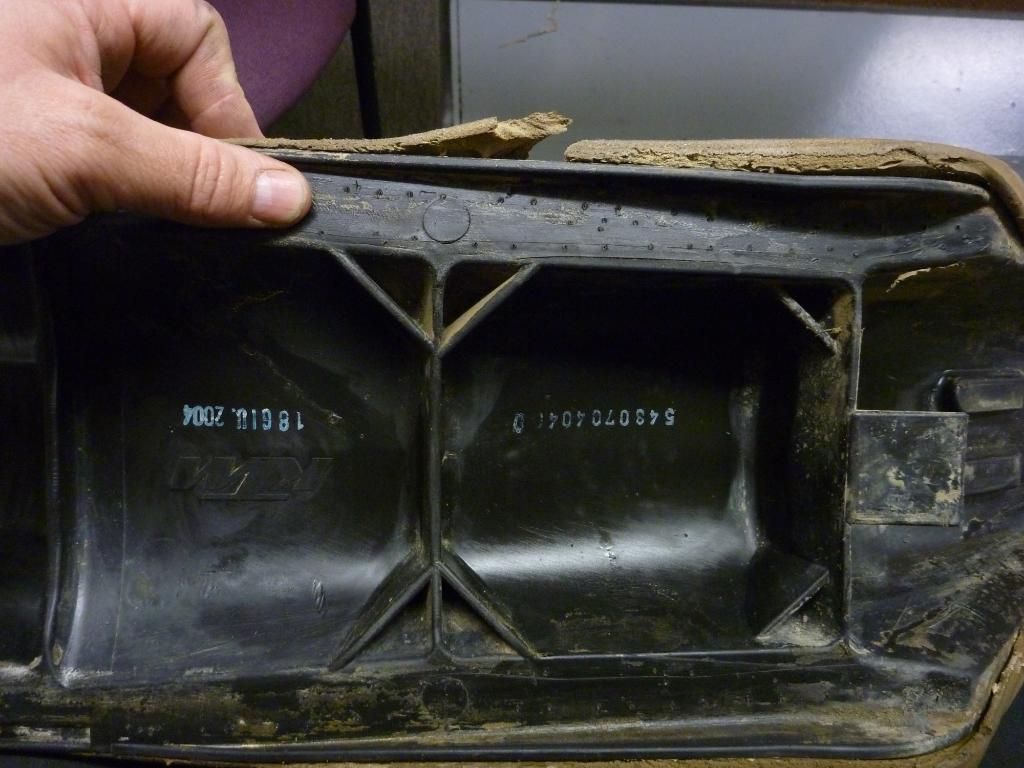
Step Two: Clean off the crap from under the seat and use a wire brush to clear as much old glue as possible. Using glue isn’t absolutely necessary I suppose but I find it helps to control the application of the cover.
.

Step Three: Repair any damage to the foam. Here you can see that not only is it torn but that there is also a small piece missing from the seat. I had some foam laying around so I glued it in place, making it slightly bigger than the hole as the foam was a little softer than the original.
.
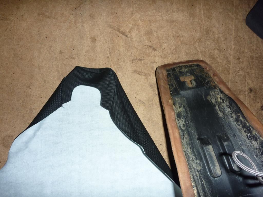
Note: you’ll be glad to know that the front part of the cover is actually shaped for the seat so that is one less thing to worry about.
.
Note: You can see here that the cover is only just long enough when it’s laid on the seat. Well actually it looks too short but that is because the cover needs to be stretched over the foam to make it fit nice n tight without folds and wrinkles.
Step Four: Spray the edge all the way around with contact glue.
.
Step Five: Fit the front of the seat and then pull the rear of the cover until it overlaps the seat and fold down onto the glue. This will hold it in place long enough to pop one staple in place.
.
.

Note: So this is what it’ll look like. The top part should be nice and tight. If it isn’t then you have one of the older covers and you’ll need to pull some more round the lip.
.
.
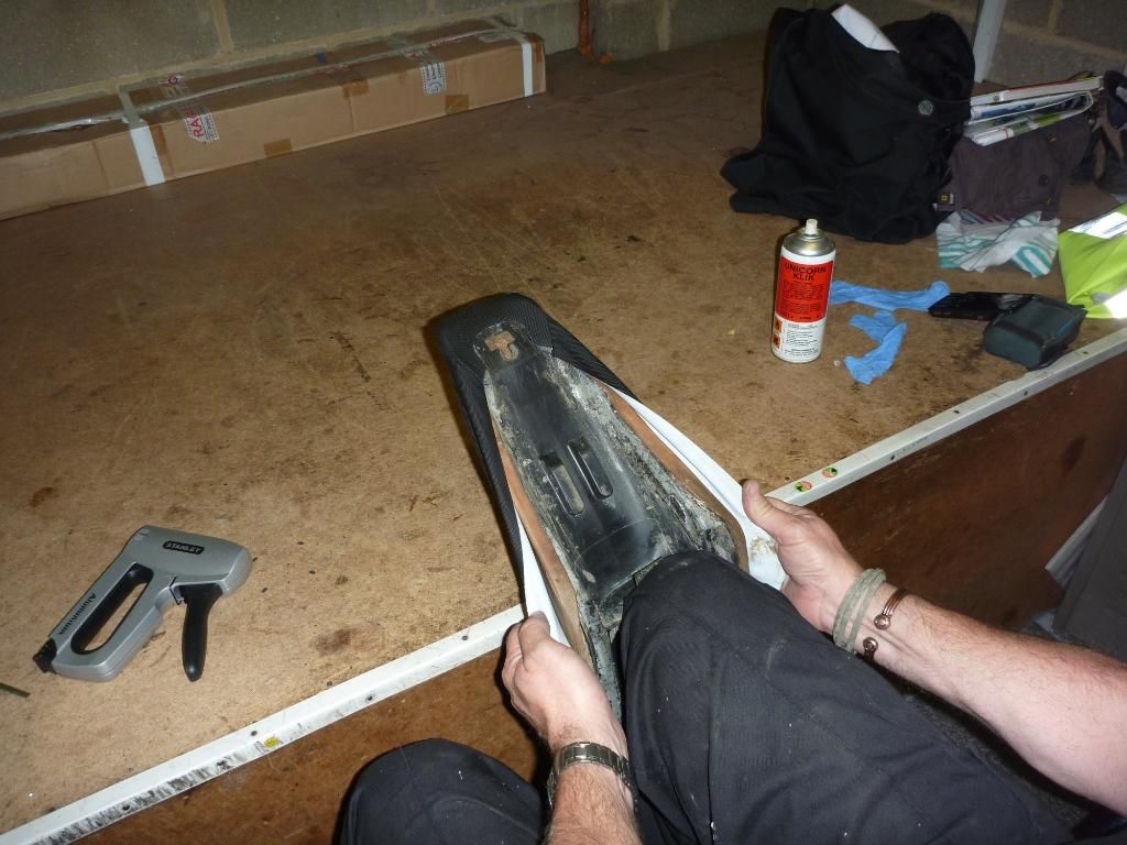
Step Six: Grip both side of the seat and using a fair amount of force (but be gentle) pull the cover until it’s good and tight and then press down onto the glue.
.
.
Step Seven & Eight: With the glue holding the cover in place get the staple gun and pop a few staples in to make sure the cover does not move. Now it’s time to double checks it’s tight enough. Too lose and it’ll show wrinkles once you sit on it for a bit. If you need to stretch it a bit more just peal the cover edges of the seat and pull it a little tighter.
.
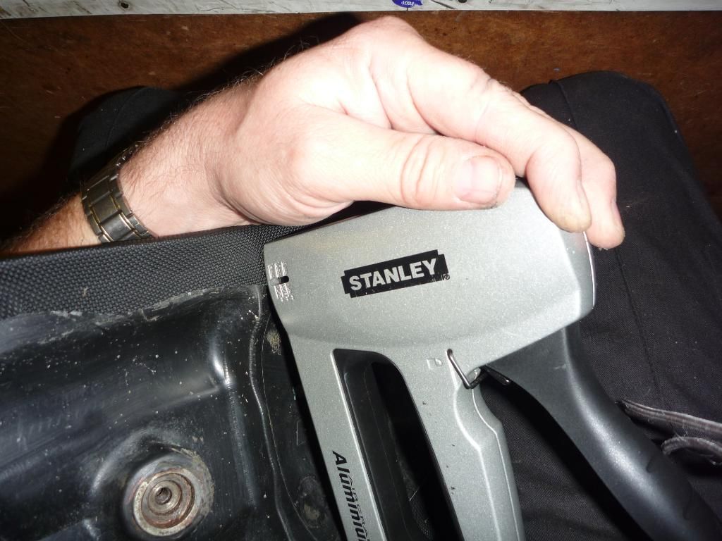
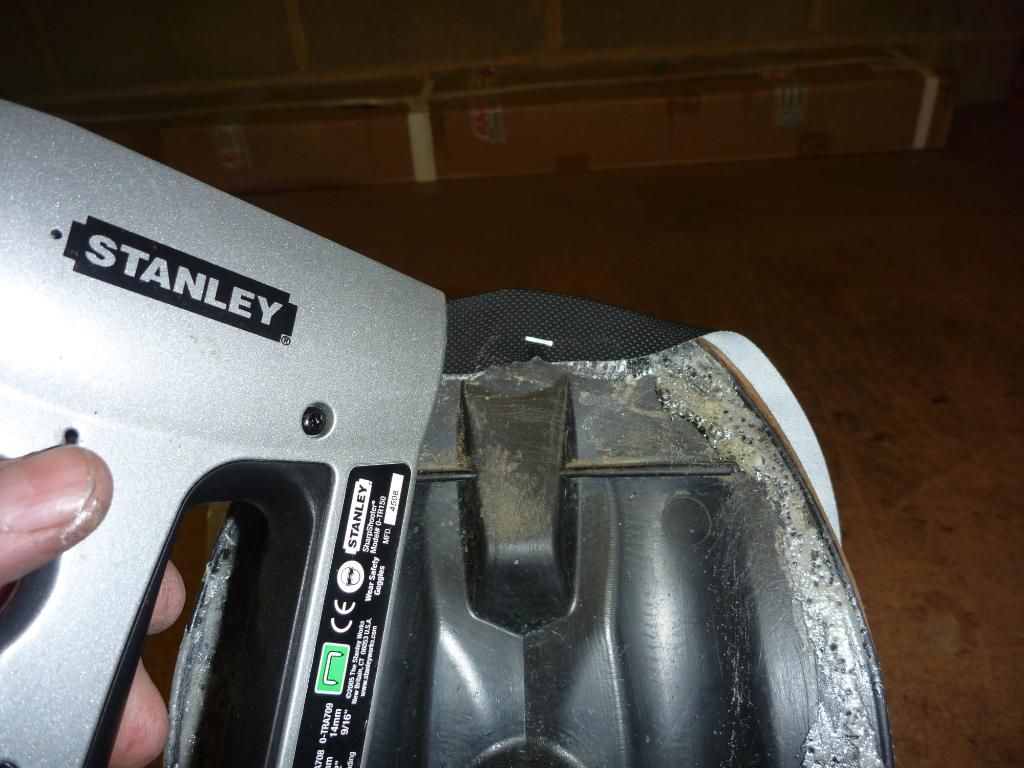
Step Nine: Staple all around the edges of the seat. The plastic is pretty tough so you’ll need to put a lot of pressure on the staple gun. I find the best way to do it is to hold the gun using one hand as shown and fire the trigger with the other. This stops the gun jumping and you get a proper staple. If not then see below for what happens.
.
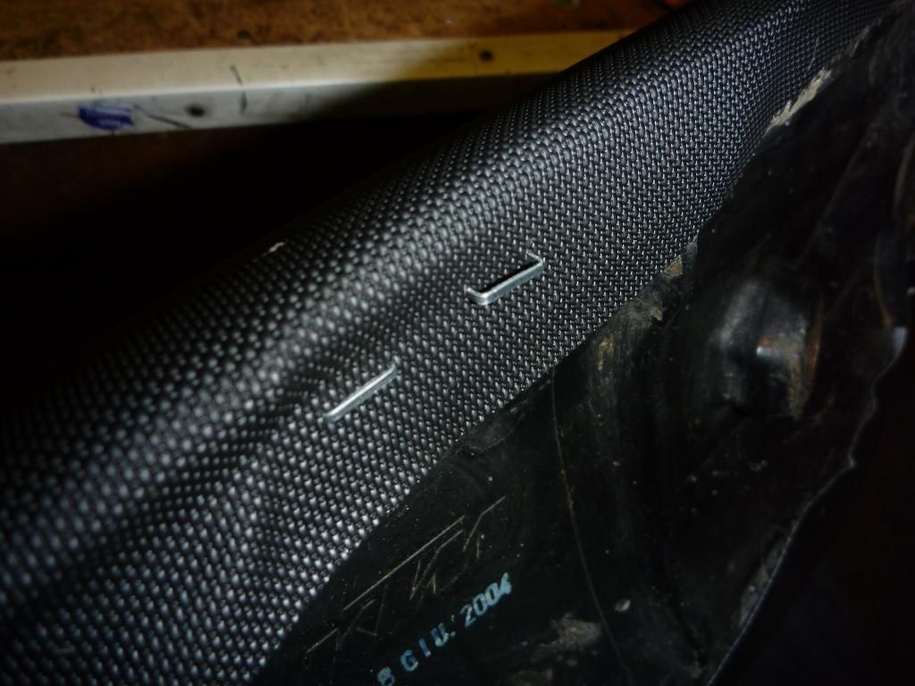
if the gun is not held very tight against the seat it'll not strike home all the way
.
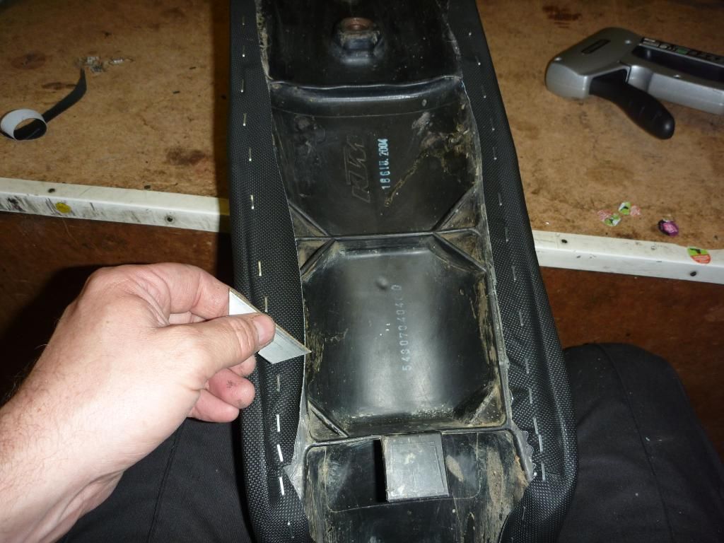
Step Ten: Trim any excess that might be getting in the way.
.
.
Ta Da! One new seat. All ready to grip my little (?) muddy botty next time I go play in the mud
.........................................................................
Time to Finish The Engine!
Now anyone who says there is no such things as gremlins (that go into the garage late at night and mess with your shit) it just plain lying – I should know!
So I left the engine the last time with the rivet link pressed through the timing chain and waiting for the job to be completed. Friday I had a day off from building bikes and got stuck into something even more fun. Doing housework and folding washing – yay!
So Saturday morning I was up at the crack of 9.30 to continue the re-build. Putting the rivet link’s side plate on I used a small socket and water pump pliers to press the plate home over the centre pins. Then I broke out the rivet tool once more and used that to flare the central pins out. Having never had this type of tool before I was a little sceptical about how well it worked but looking at the photo I must admit it looks pretty good. However at the time I was less sure so I dug out the old metal weight and the ballpeen hammer to give it a bit of a going over – just in case.
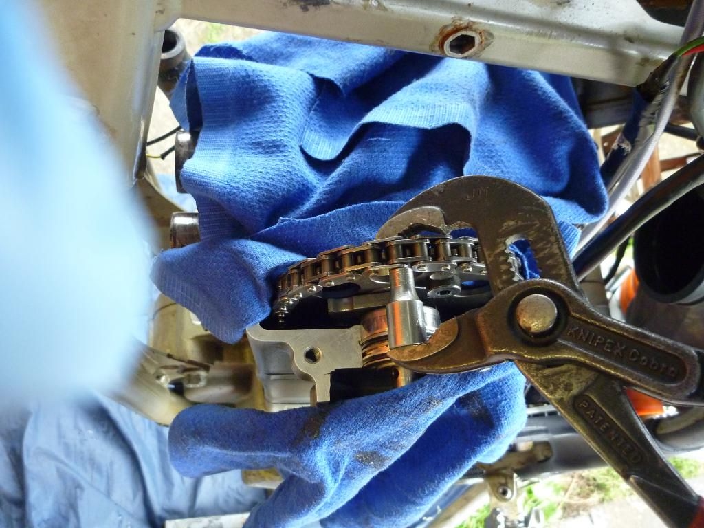
using the pliers and socket to press home the side plate
.
finishing off the rivet link
.
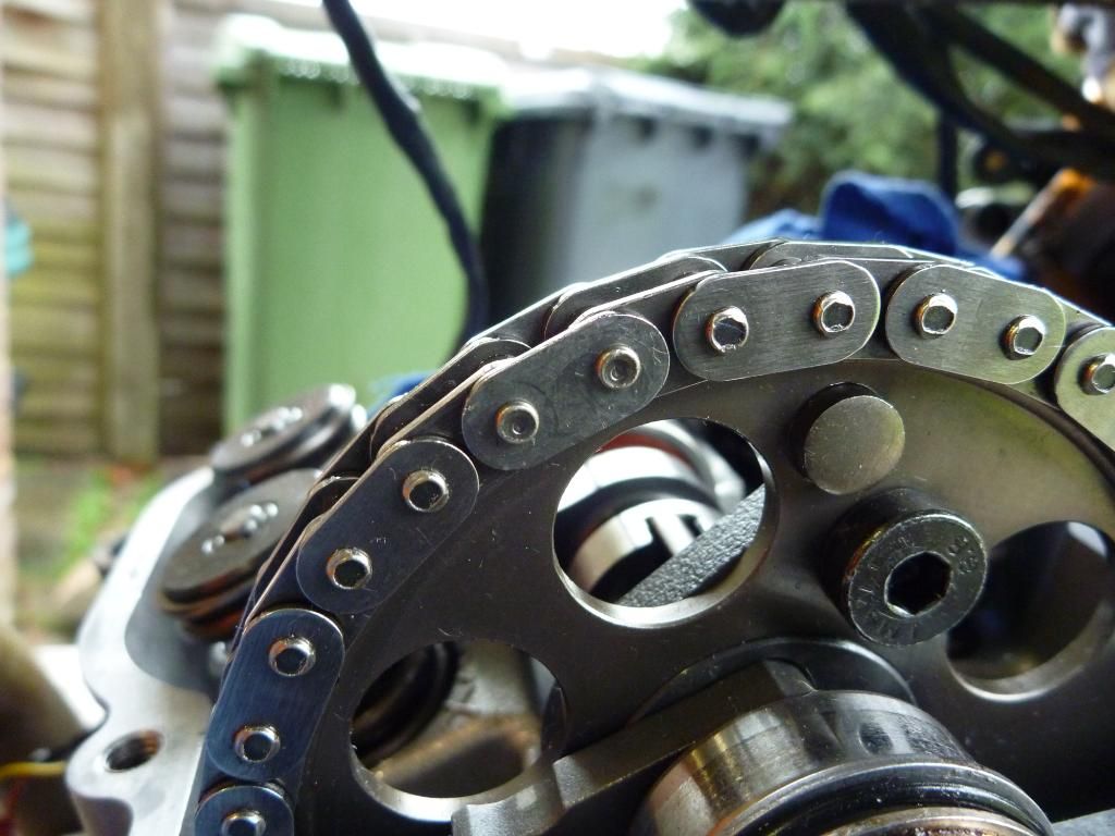
you can see how the tool dimpled the pins.
.
still gave it a few tap though! you can use this method if you don't have a rivet tool.
use a 4lb hammer at the back if you have one
.
Next I double checked that the sealing surface of the valve cover and the head were unmarked and used a bit of wet and dry to dress them up a bit after running the flat edge of a stanely knife along it to help smooth out any slight imperfections. Like I said earlier it’s important to make sure there is a good seal as no gasket it used here, only a thin coating of sealant. After dabbing a little all along the edges I slipped the cover back on. At first it doesn’t look like it’ll fit but it goes on quite easy once you know how. Taking the bolts from the piece of cardboard I slipped them in one by one until I got to the last one. Then cursed and took them all back out again and had to lift up the valve cover. For reasons only know to KTM there in one bolt that you can’t get into place once the cover is down flat. You have to slip the bolt into its hole while the cover is still only semi on.
.
you can see the thin layer of sealant on the valve cover.
.
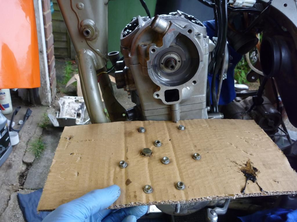
cardboard with the bolts saved in the correct order.
.
this is the one that you have to put into the hole while the cover is still loose
(not sure if other KTM's are like that - maybe the previous owner mixed them up?)
So now the only job left was to check and adjust the valves and I could get on with putting the rest of it back together. If only it was that easy!
checking the valve gaps. factory is .120 but you try and find a feeler gauge that has that size!
in the end i got one from machine mart that has a .127 gauge and that is close enough for me
.
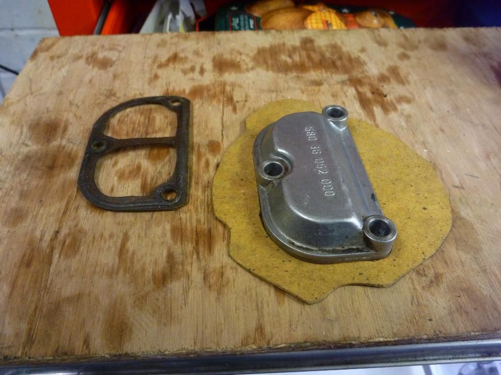
Once I’d set all the valve gaps I replaced the covers but noticed one of the gaskets was damaged. As these were not in the set I bought for the engine I resorted to the old method and cut out my own.
I used the cover as a template to draw the outline and then used a long reach punch down the bolt holes to mark out the location of the holes. Then I cut them out using another punch designed for the purpose. Next I used the old gasket to mark out the internal sizes. Now it was a simple case of cutting the whole lot out with a scalpel – job done.
dawing the outer size
.
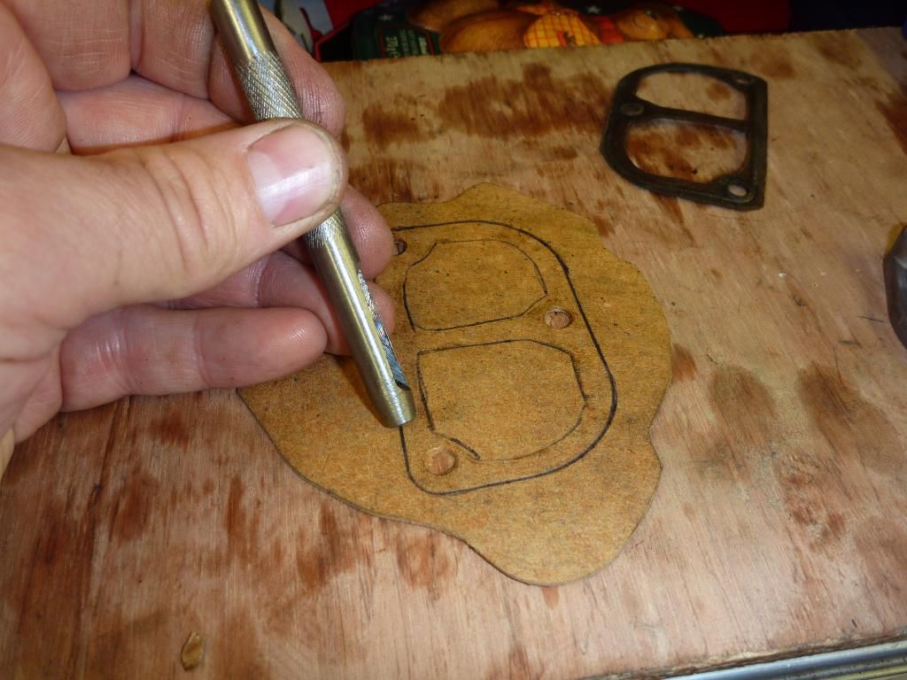
cutting out the bolts holes
.
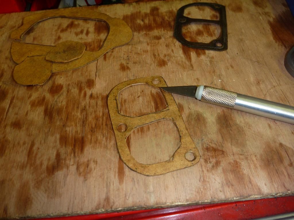
cutting out the final gasket. job done
.
The water pump went on without a hitch, but I did need to reform the clirclip slightly. The cam chain tentioner was fitted next and that was pretty much that.
waterpump installation
.
Now being a cautious type I thought I’d use the nut on the end of the crank to slowly turn the engine over just to be on the safe side. I fitted a 17mm ring spanner and very carefully turned the engine round. With no plug in the head there was no resistance so I could feel if everything was ok. Working very carefully saved the day as I could feel that the valves were out of sync. How the hell could that of happened? I’d locked the crank in place and when I fitted the cam the dots had lined up with the head surface. So what had gone wrong?
Anyway there was nothing for it but to take of the valve cover again and double check it. sure enough the dots no longer lined up! What the F***! How did that happen?? I thought I was really careful so what went wrong? I’ve still no idea what happened, maybe I was messing about with the chain when putting the clink in and I moved the cam by mistake – who knows?
Anyway I now had a bit of a quandary again. The chain needed to be split to move the cam sprocket and I was all out of spare links! Nothing for it but to split the chain on the rivet link again, better that then the long trek back to a dealer for a spare. It pressed out fine and popped back in without an issue. Once I double checked the crank was properly locked in the correct position the cam was lined up and the rivet link reinstalled. Valves re-adjusted and the engine was ready to go – again. More careful turning of the crank did not result in any valve piston interface so I loosened the crank and connected the battery once more. A quick press of the button and a satisfying whirling come out of the engine.
Oh yes I’m leaving out one important part. While checking the valve clearances I managed to nearly knock myself out on the handlebars! I stood up and the RHS metal edge of the hand guards dug into my scalp, while simultaneously ringing the bells in the clock tower. Hurt? Just a bit. In fact there is some skin and a couple of hairs on the end of the bars in the photo. Hairs I can dearly afford to lose I might add!
look carefully and you'll see some skin on the end of the guard and a couple of hairs!
.
So the engine was complete, all the covers were on and ......looked like shit. The engine covers on both sides had been peeling off for ages (like most KTM’s) and really didn’t look nice. Cue one tin of nitomorse paint stripper and within no time the old flaky paint was off. But this left some dark bits and some new shinny bits. Bring on more chemicals! I used some ‘wonder wheels’ cleaner and that darkened up the cases nicely to give a uniformed ‘weathered’ look.
.
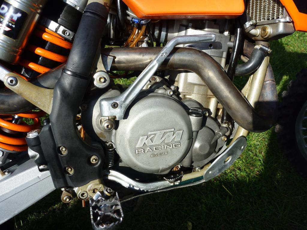
paint on the cases removed. looks better now.
.
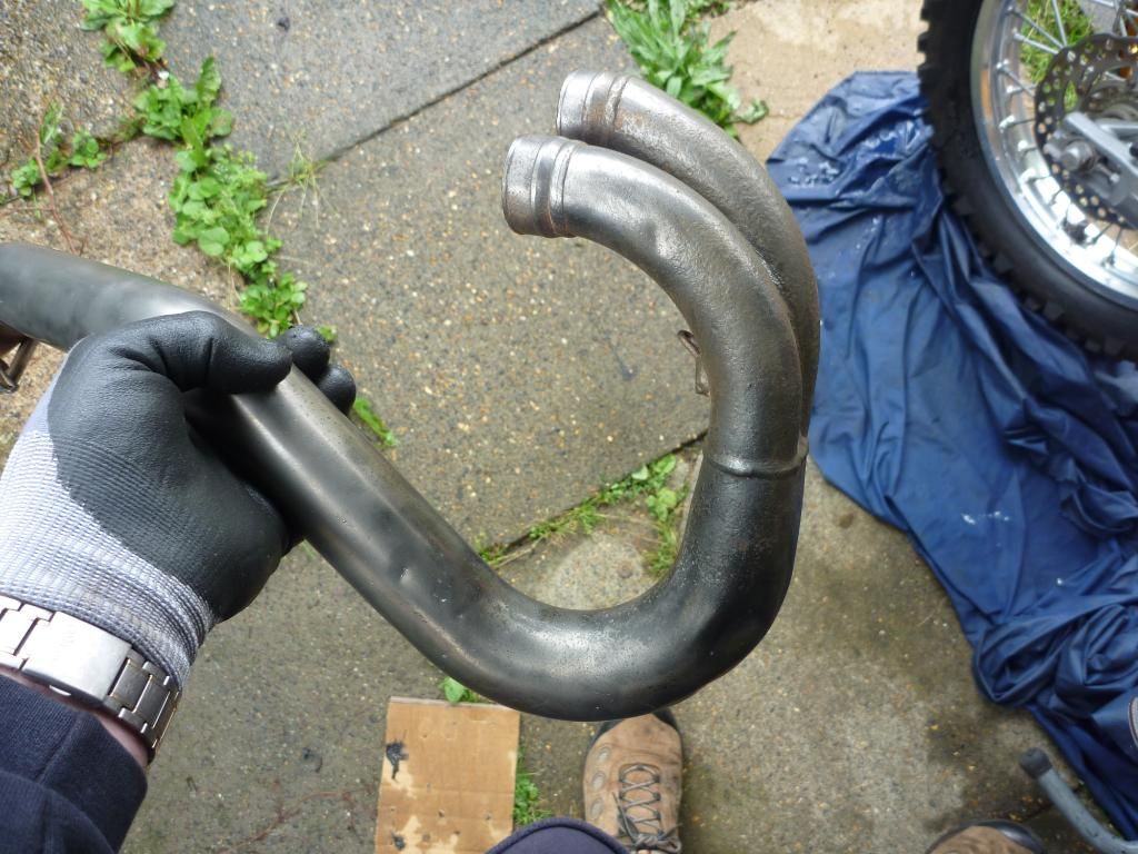
exhaust - cleaned with a wire brush on an angle grinder
.
So now I could put it off no longer - Definitive Moment of Truth Time – starting the engine. But before I could fire it up I needed to get some oil. I’d been advised to run it in without using a fully synthetic oil, so a trip down to Halfords was in order. I slipped on the (now cleaned and re-packed) exhaust, filled the bike with oil and then thought I’d better put on the radiators as the bike tends to run better with those on! Using a 50% mix of coolant and ionised/distilled water from a bottle I filled the radiators, bleeding the engine and rhs radiator as required. I slipped the tank in place, connected the fuel. Moment of truth time.
Choke out, pressed the button and............... vroom! One press and it fired! I let it idle for a while to move the water around the rads and to settle the engine then switched it off to get some more of the bodywork fitted. By now my girlfriend was pestering me to finish up as I need to get dinner on the go. I quickly fitted the new rad scoops to see what my new bike would be like but the RHS scoop would not fit properly. I traced one issue to a jubilee clip being around the wrong way and it was catching on the tank. Another problem was some electrical gubbins under the tank not allowing the tank to sit 100%. After that the LHS was fine but the RHS would still no sit correctly. Everything else looked fine and the tank/rads looked ok too so I took the executive decision to trim the shroud that makes contact with the side of the radiator. Once everything fitted I popped the seat on and stood back for a quick look. Nice – time for dinner and some Jacks!
.
getting there! bodywork quickly laid on the bike to see what it'll look like
......................................................
.
.
Sunday: today I was going to do all of the little things that need doing to tidy the bike up and finish it off. First of all I completed the installation of the rad scoops and fitted a couple of ‘E’ clips to the bolts to keep them in situ when removing the scoops/tank. This is well worth doing as it stops you digging around in the mud/grass at a race meeting or on the side of the trail if you need to take the tank off. I also do the same with the seat bolt as this is another one that tends to fall out and disappear. It makes refitting the seat slightly more tricky but the benefit of not losing the bolt outweighs that. The only thing you have to remember is to pull slightly up on the seat when you remove it otherwise the bolt will turn itself out of the clip.
.
'E' clip on the rad scoop bolts
.
also on the seat bolt
.
Now that the tank etc was lined up ok it was time to turn my attention to the rear end. I could see the rear was slightly skew so I removed the tailpiece and measured from the swingarm up to each side of the subframe. The LHS was clearly out so a few tugs with a pole soon sorted that out.
.
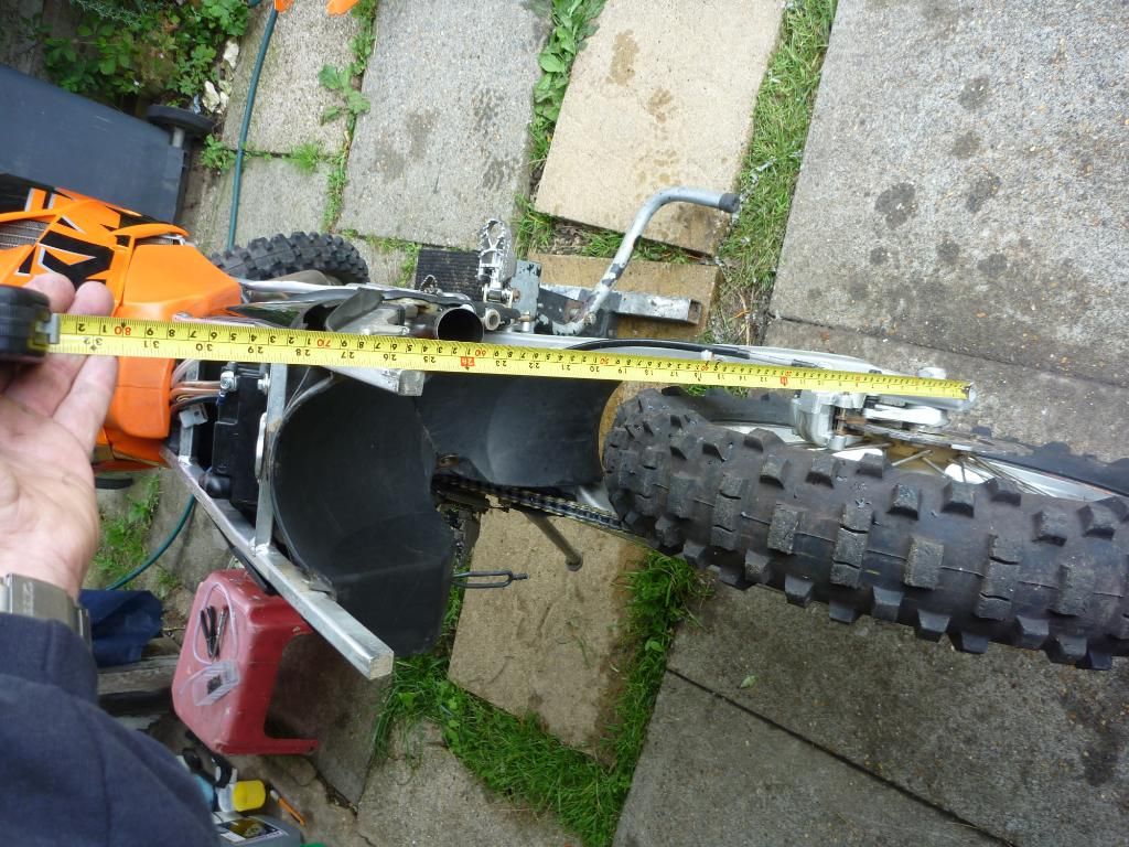
measuring to check the sub-frame
.
sub-frame adjustment tool!
.
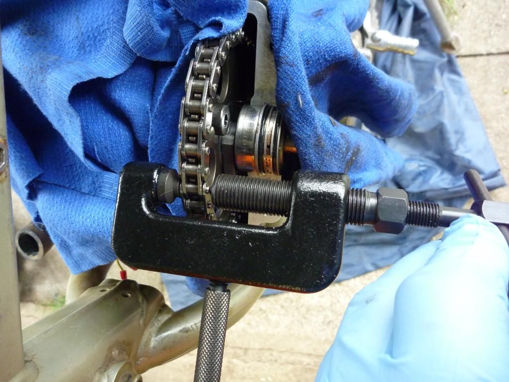
Seeing as I’d replaced the swingarm chain wear guide I thought I might as well finish it off and replace the other two as well so while I was picking up the new number board I bought those too. I thought about polishing up the rear aluminium carrier but decided to skip that for today. To fit the new rear guide the chain had to be split. That wasn’t a problem as I’d used a split link the first time but once the guide was in place I opted to use the supplied rivet link. Seeing as this is a real heavy duty chain I decided to rivet it the old fashioned way and used the ballpeen hammer and a weight. Pressing on the side plates was more difficult this time so I used a small G-clamp. This has a hollow central pressy bit so it's ideal for pressing links on.
.
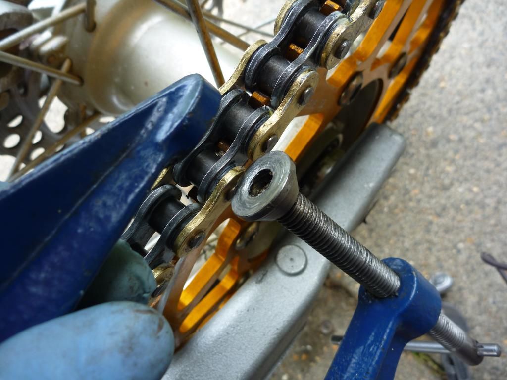
g-clamp used to press home the side plate
.
The front guide was well worn so that was due a change. Then I fitted the new bling gear lever but should have done that while the front chain guide was off as now I had to hold that down while using the ratchet. A handy cable tie held it in place while I worked.
.
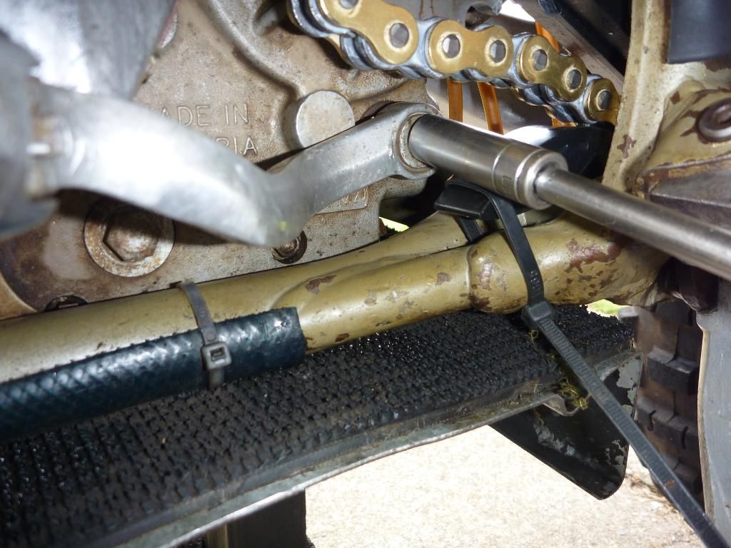
new slider fitted and now for a new gear lever (not show)
.
Now I move up to the front of the bike. I’d noticed the thread on the fork guard was stripped earlier so I set about repairing that. First I drilled out the lower leg. The tapped it out to M8 and turned in the replacement thread. Used bearing fit on the thread to make sure it remains in place. Then the dremel came in hand again to cut of the exposed thread left over. Job done.
.
the thread incert i was going to use to repair the thread
drill out the old thread

re-tap the new thread to M8
cutting the left over thread
and that was that - the bike was more or less finished!
.
Sunday afternoon I took it for a little ride to bed it in slightly and for that I fitted my old race wheel that has a tube/trails tyre fitted to save the rear tyre/mousse. It all held together but I took nice and easy on the engine. I’ll try and sort out another front wheel with a tube in to get some proper mileage on it to run it in quicker
.
............................Monday: I tried the number board for size and for some reason ktm does not use the rubber straps to hold it on. They use a central bolt arrangement. I could see the hole in the top yoke that was no doubt used for it, but the speedo bracket was in the way. I trimmed it with a dremel and also used a bit of heat to reposition the front part to clear the lug on the board.
Before all of this though I had to give it all a jolly good clean as it was so packed with dust. Seeing a broken wire I set about trying to find out were it went and in doing that stripped out a load of redundant wires and bits and pieces.
.
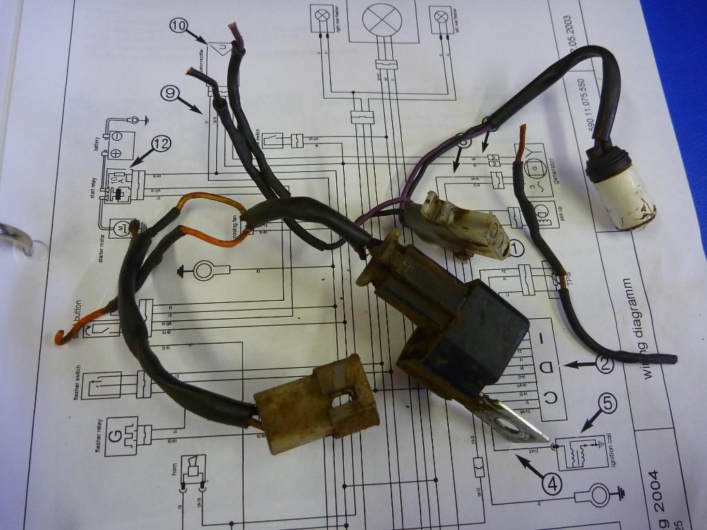
these were not required any more
bolt used to hold the new number board on
.
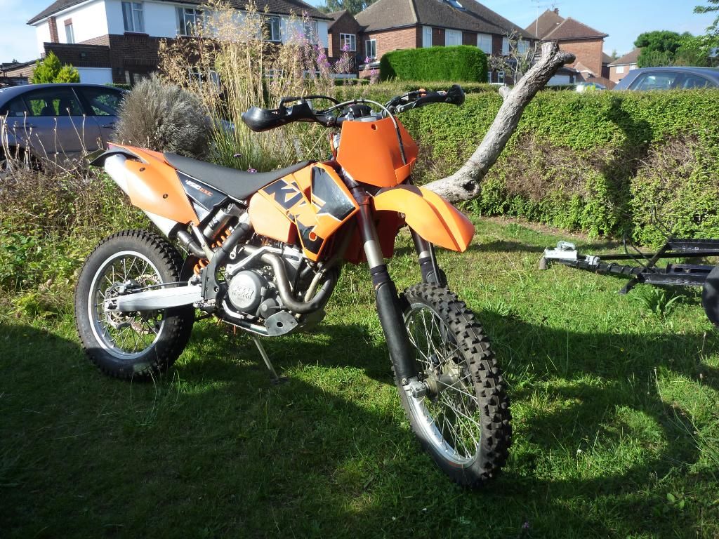
not a very good photo as the sun washed out the colour of the plastics.
i'll try and sort one out soon. you can at least see the new front number board
.
I tried loads of different ideas but in the end I settled on using a small copper pipe to use a spacer. This would hold the board in the correct location and was thin enough to clear all the brackets. Oh yes I also found where the broken wire came from and while I couldn’t get it reconnected to the connect block I simply used another connector to joint the two wires – and now I have a hooter again!
.
If you enjoyed this report and would like to be notified of new reports or web site updates then join the mailing list. To sign up to the list just click HERE>> and send me an email.